Text Solution
Verified by Experts


Similar Questions
Explore conceptually related problems
Recommended Questions
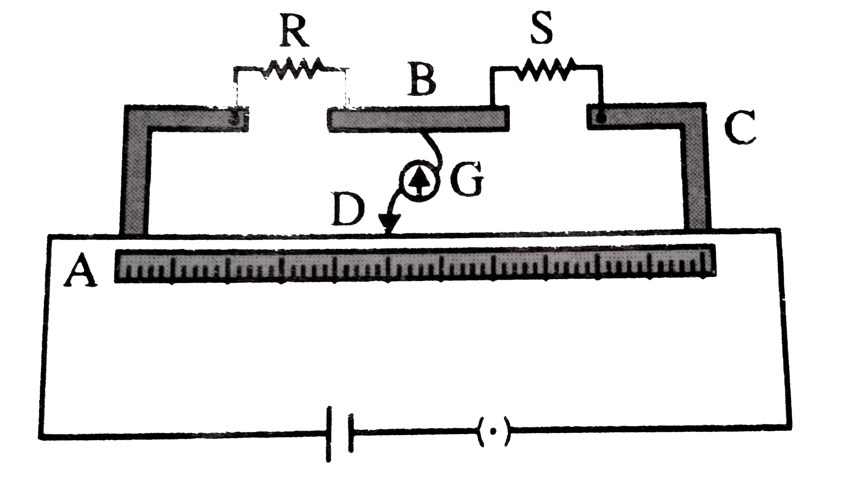
- Circuit diagram of metre bridge is shown in figure. The null point is ...
Text Solution
|
- In meter bridge, the null points is found at a distance of 60.0 cm fro...
Text Solution
|
- In a meter bridge, the null points is found at a distance of 33....
Text Solution
|
- In a meter bridge, the null point is found at a distance of 40 cm from...
Text Solution
|
- In a meter bridge , the null point is found at a distance of 36.7 cm f...
Text Solution
|
- In a metre bridge the null point is found at a distance of 35 cm from ...
Text Solution
|
- In a meter bridge, the null point is found at a distance of 40 cm from...
Text Solution
|
- In a meter bridge the null oint is found at a distance of 33.7 cm from...
Text Solution
|
- In a meter bridge the null oint is found at a distance of 33.7 cm from...
Text Solution
|