A
B
C
D
Text Solution
Verified by Experts
The correct Answer is:


Topper's Solved these Questions
Similar Questions
Explore conceptually related problems
ALLEN -CURRENT ELECTRICITY-EX.II
- The potential difference between the terminals of a cells is found to ...
Text Solution
|
- What is the reading of ammeter is adjoining circuit diagram.
Text Solution
|
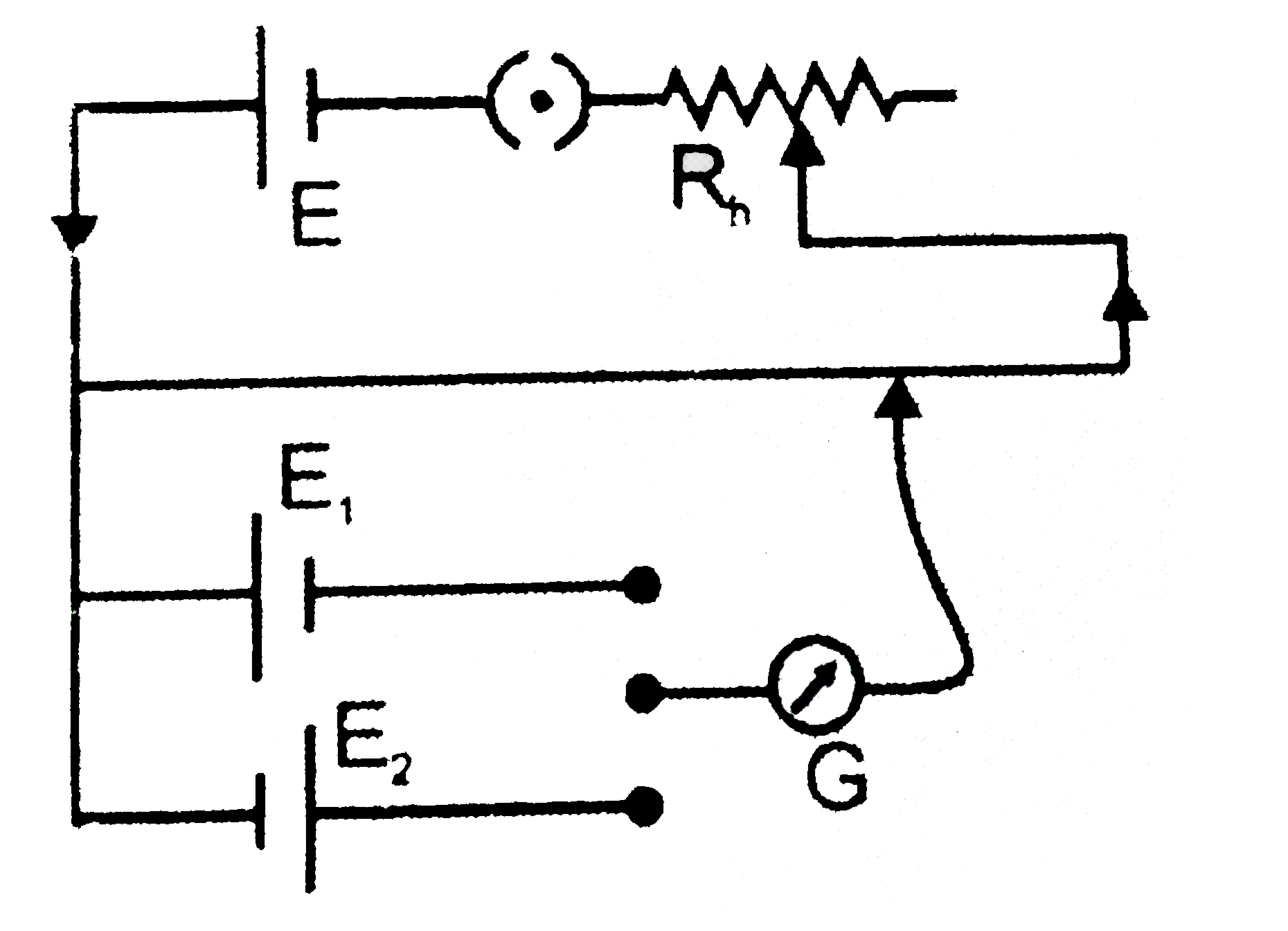
- The following diagram shows the circuit for the comparision of e.m.f. ...
Text Solution
|
- In the following circuit the reading of the voltmeter will be:-
Text Solution
|
- In the following diagram the deflection in the galvanometer in a poten...
Text Solution
|
- In the circuit shown the resistance of voltmeter is 10000 ohm and that...
Text Solution
|
- Value of Current i in the following circuit is:-
Text Solution
|
- The resistance of galvanometer is G ohm and the range is 1 volt. The v...
Text Solution
|
- The total resistance between x and y in ohm is:-
Text Solution
|
- In an experiment to measure the internal resistance of a cell by a pot...
Text Solution
|
- There are n similar conductors each of resistance R . The resultant re...
Text Solution
|
- A galvanometer of resistance 100Omega gives full scale deflection for ...
Text Solution
|
- If only 2% of the main current is to be passed through a galvanometer ...
Text Solution
|
- In the following circuit diagram the value of resistance X for the pot...
Text Solution
|
- The sensitivity of a potentiometer is increased by
Text Solution
|
- A potential gradient is created in the wire by a standard cell for the...
Text Solution
|
- A voltmeter having a resistance of 998 ohms is connected to a cell of ...
Text Solution
|
- Find the potential difference between X and Y in volt is:-
Text Solution
|
- A cell of e.m.f. 2V and negligible internal resistance is connected to...
Text Solution
|
- Potentiometer wire length is 10m, having a total resistance of 10Omega...
Text Solution
|