A
B
C
D
Text Solution
Verified by Experts
The correct Answer is:


Similar Questions
Explore conceptually related problems
Recommended Questions
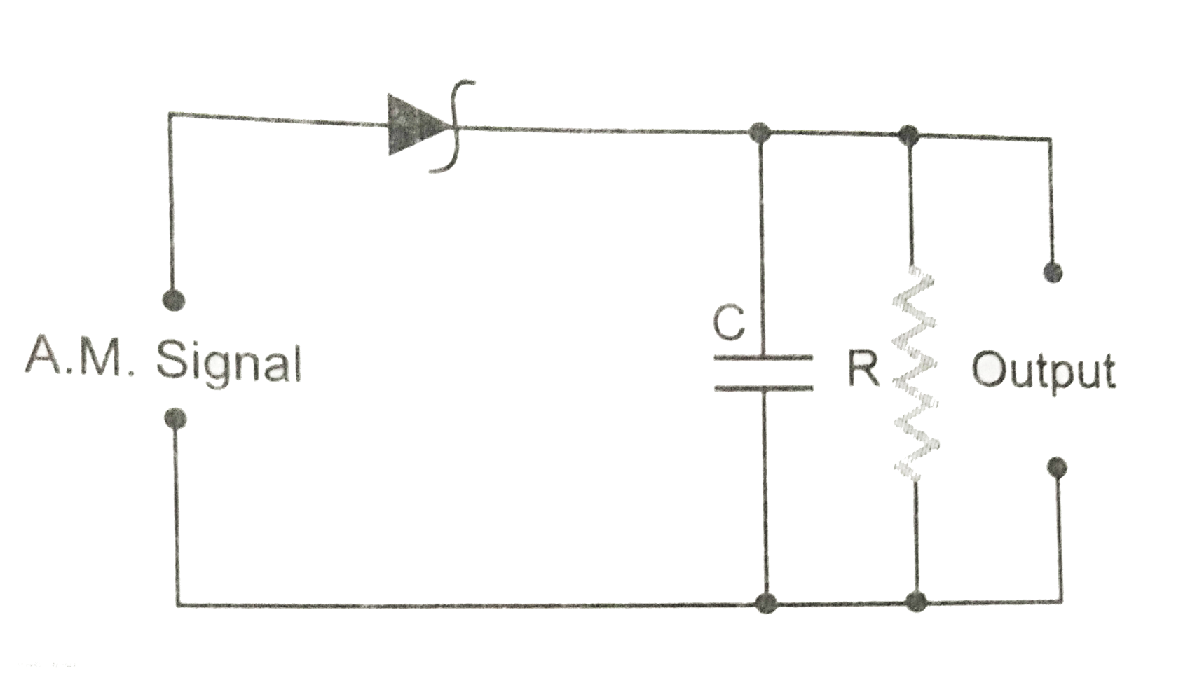
- Fig. 10 (CF).1 is the circuit diagram of an AM demodulator. For good d...
Text Solution
|
- In a diode AM- detector, the output circuit consist of R=1 k Omega and...
Text Solution
|
- Given below a circuit diagram of an AM demodulator. For good demo...
Text Solution
|
- Fig. 10 (CF).1 is the circuit diagram of an AM demondulator. For good ...
Text Solution
|
- In a diode AM- dectector, the output circuit consist of R=1 kW and C=1...
Text Solution
|
- A message signal m(t)=4cos2000pit modulates the carrier C(t)=cos2pif(c...
Text Solution
|
- In a diode AM- dectector, the output circuit consist of R=1 kOmega and...
Text Solution
|
- एक आयाम मॉडुलित तरंग के विमोडुलेशन के लिए परिपथ दिया गया है। f वाहक आ...
Text Solution
|
- Assertion : FM broadcast is preferred over AM broadcast . Reason...
Text Solution
|