Text Solution
Verified by Experts


Similar Questions
Explore conceptually related problems
Recommended Questions
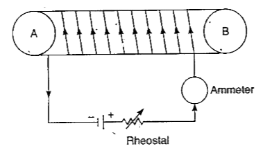
- Tlie figure shows a circuit containing a cotl wound over a long and ho...
Text Solution
|
- Calculate the current show by the ammeter A in the circuit diagram
Text Solution
|
- The figure shows a solenoid wound on a core of soft iron. Will the end...
Text Solution
|
- Two solenoids, 'P' and 'Q' are taken. The coil in solenoid 'P' is woun...
Text Solution
|
- परिनालिका से आप क्या समझते है। एक लम्बी धारावाही परिनालिका के द्वारा उ...
Text Solution
|
- Draw a diagram of the tube, showing the results of your activity.
Text Solution
|
- In the diagram XY is a long solenoid of insulated wire wound on a card...
Text Solution
|
- Draw a circuit diagram showing the biasing of a photodiode.
Text Solution
|
- Draw a circuit diagram to show how a photodiode is biased.
Text Solution
|