Text Solution
Verified by Experts


Similar Questions
Explore conceptually related problems
Recommended Questions
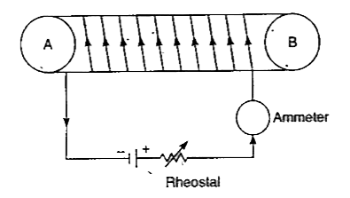
- Tlie figure shows a circuit containing a cotl wound over a long and ho...
Text Solution
|
- A thin but long, hollow, cylindrical tube of radius r carries a curre...
Text Solution
|
- The magnitude of the magnetic field inside a long solenoid is incr...
Text Solution
|
- एक लम्बी तांबे की नली में धारा प्रवाहित की जाये तो नली के अंदर चुम्बकी...
Text Solution
|
- A wire of length 100 m is tightly wounded on a hollow tube of radius 5...
Text Solution
|
- A wire of length 100 m is tightly wounded on a hollow tube of radius 5...
Text Solution
|
- The magnitude of the magnetic field inside a long solenoid is increase...
Text Solution
|
- The strength of a magnetic field inside a long current-carrying straig...
Text Solution
|
- By increasing the number of turns in the coil, the strength of the mag...
Text Solution
|