A
B
C
D
Text Solution
Verified by Experts


Topper's Solved these Questions
ELECTRIC CURRENT AND ITS EFFECTS
BEIITIANS|Exercise IIT JEE WORKSHEET (I. Single Correct Answer Type)|19 VideosELECTRIC CURRENT AND ITS EFFECTS
BEIITIANS|Exercise IIT JEE WORKSHEET (II. Multiple Correct Answer Type)|1 VideosELECTRIC CURRENT AND ITS EFFECTS
BEIITIANS|Exercise SUMMATIVE WORKSHEET|23 VideosHEAT
BEIITIANS|Exercise IIT JEE Worksheet (V. Matrix Matching)|4 Videos
Similar Questions
Explore conceptually related problems
BEIITIANS-ELECTRIC CURRENT AND ITS EFFECTS-HOTS WORKSHEET
- It is impossible to construct a torch in the absence of
Text Solution
|
- Among the labelled parts, current does not flow through the
Text Solution
|
- The given figure shows a circuit with a cell connected to a bulb and a...
Text Solution
|
- Suraj has constructed a simple electric circuit. It consists of a bulb...
Text Solution
|
- Raju has constructed four different circuits with four bulbs, four cel...
Text Solution
|
- Raju bought five similar bulbs and connected them with two cells to co...
Text Solution
|
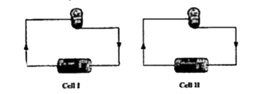
- The given figure shows two circuits, each consisting of a bulb and a c...
Text Solution
|
- A circuit is constructed using two torch bulbs and a cell, as shown in...
Text Solution
|
- Various parts on the outer surface of an electric cell are labelled as...
Text Solution
|
- Which of the following parts of a torch is not paired with its functio...
Text Solution
|
- Raj performs an experiment to know the conducting nature of some of th...
Text Solution
|
- The schematic diagram of an open circuit is shown in the given figure....
Text Solution
|
- The picture of a household torch is shown is the given figure. Th...
Text Solution
|
- Different arrangements of an electric bulb with an electric cell are s...
Text Solution
|