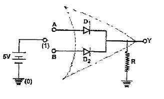
OR gate with diodes : An OR gate may be constructed using transistor or relay circuits or diodes Fig shows the OR gate . This gate consists of two diodes `D_(1)` and `D_(2)` which are connected in parallel across the output Y. working of this circuit can be explained as follows :
(i) When A is (+5 V) and B is (0 V) then diode `D_(1)` is forward biased and hence it conducts. Diode `D_(2)` is reverse biased and hence no current flows through it . Current through diode `D_(1)` flows via resistor R. Hence there is a potentials drop across R. Thus Y is high .
(ii) When B is 1(+5) and A is 0(0,V) then diode `D_(2)` is forward baised and hence conducts. Diode `D_(1)` is reverse biased , no current flows through it . Current through diode `D_(1)` flows via resistor (R) . Hence there is a potential drop across R. Thus Y is high.
(iii) When A = 1 and B = ! . In this case both the biodes are forwards biased and hence they conduct. Current through these diodes flows via resistor R. Thus , there ios a potenital drop across R. Hence Y is high.
(iv) When A = 0 and B= 0 , no current will flow through either of the diodes and hence there is no potenital drop across R. Hence Y is low .