

A
B
C
D
Text Solution
Verified by Experts
The correct Answer is:


Topper's Solved these Questions
SEMICONDUCTORS
ALLEN|Exercise Part-3(Exercise-3)|27 VideosSEMICONDUCTORS
ALLEN|Exercise Part-3(Exercise-4)|51 VideosSEMICONDUCTORS
ALLEN|Exercise Part-3(Exercise-1)|84 VideosPHYSICAL WORLD, UNITS AND DIMENSIONS & ERRORS IN MEASUREMENT
ALLEN|Exercise EXERCISE-IV|8 VideosWAVES AND OSCILLATIONS
ALLEN|Exercise Part-1(Exercise-05)[B]|42 Videos
Similar Questions
Explore conceptually related problems
ALLEN-SEMICONDUCTORS-Part-3(Exercise-2)
- Given below are four logic gates symbols. NAND, NOR and OR are respect...
Text Solution
|
- The output Y of the combination of logic gates shown is equal to
Text Solution
|
- Which of the following relation is valid in Boolean algebra :-
Text Solution
|
- The output of given logic circuit is
Text Solution
|
- The following configuration of gate is equivalent to
Text Solution
|
- To get an output 1 from the circuit shown in the figure, the input mus...
Text Solution
|
- The circuit shown here is logically equivalent to :-
Text Solution
|
- Which of the following will have an output of 1 :-
Text Solution
|
- The logic symbols shown here are logically equivalent to :-
Text Solution
|
- The combination of the gates shown in the figure produces
Text Solution
|
- The combination of the gates shown will produce
Text Solution
|
- Which of the following represents correctly the truth table of configu...
Text Solution
|
- The truth table for the following combination of gates is :-
Text Solution
|
- The combination of the gates shown represents :-
Text Solution
|
- Which of the following relations is valid for Boolean algebra :-
Text Solution
|
- In the following circuit, the output Y for all possible inputs A and B...
Text Solution
|
- The real time variation of inputs are fed into NAND gate, then select ...
Text Solution
|
- The time variations of signals are given as in A,B and C. Point out th...
Text Solution
|
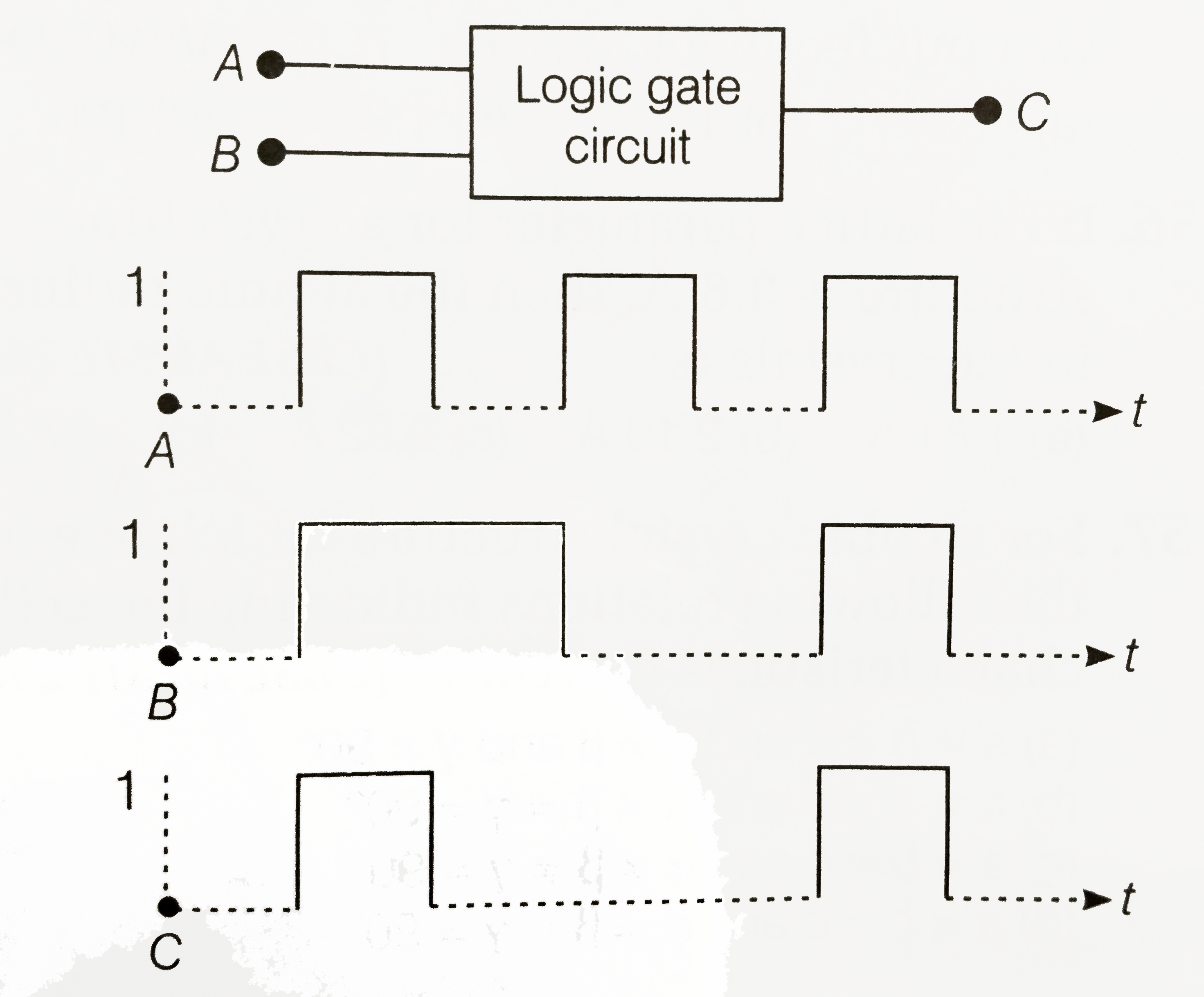
- The following figure shows a logic gate circuit with two inputs A and ...
Text Solution
|
- Select the output Y of the combination of gates shown in figure for in...
Text Solution
|