Home
Class 12
PHYSICS
If the readings V(1) and V(3) are 10. vo...

If the readings `V_(1)` and `V_(3)` are 10. volt each, then reading of `V_(2)` is:

A

0 volt

B

100 volt

C

200 volt

D

cannot be determined by given information.

Text Solution

Verified by Experts

The correct Answer is:
C

`because` L,R,C are in series
So amount of current will remains same through each.
Here `V_(1)=V_(3)` or
`iX_(L)=iX_(C)` so `[X_(L)=X_(C)]`
So circuit will behave as pure resistive ckt so `V_(2)=200V`
Promotional Banner

Topper's Solved these Questions

Similar Questions

Explore conceptually related problems

In the given circuit, Fig., the reading of voltmeter V_(1) and V_(2) 300 votls each. The reading of the voltemeter V_(3) and ammeter A are respectively

If the reading of volmeter V_(1) is 30 V, what is the reading of voltmeter V_(2) ?

The figure shows a portion of a circuit. Resistor are known and indicated on diagram and voltmeter are identical. If voltmeters v_(1) and v_(2) reads 7.5v and 5v respecticely then reading of v_(3)

In the figure shown R = 100 Omega L = (2)/(pi) H and C = (8)/(pi) mu F are connected in series with a.c source of 200 volt and frequency 'f' . V_(1) and V_(2) are two hot-wire voltmeters. If the readings of V_(1) and V_(2) are same then:

In the figure shown R = 100 Omega, L = (2)/(pi) H and C = (8)/(pi) mu F are connected in series with a.c source of 200 volt and frequency 'f' . V_(1) and V_(2) are two hot-wire voltmeters. If the readings of V_(1) and V_(2) are same then:

If the reading of coltmenter V_1 is 40 V, what is the reading of voltmeter V_2 ?

In an LCR series circuit, the reading of ideal voltmeters V_(1) and V_(2) are 20sqrt(2) volt and 15 volts respectively as shown in the figure (the given circuit in inductive in nature). Then

In the circuit diagram of zener diode as shown in figure, when the value of V_(0) is 8 volt, the current through zener diode is i_(1) and when V_(0) is 16 volt, the corresponding current is i_(2) . Find the value of (i_(2)-i_(1)) . (Zener breakdown voltage V_(2)=6V)

An ammeter A of finite resistance, and a resistor R are joined in series to an ideal cell C . A potentiometer P is joined in parallel to R . The ammeter reading is I_(0) and the potentiometer reading is V_(0) . P is now replaced by a voltmeter of finite resistance. The ammeter reading now is I and the voltmeter reading is V .

Voltmeters V_(1) and V_(2) are connected in series across a D.C. line V_(1) reads 80 volts and has a per volt resistance of 200 ohms , V_(2) has a total resistance of 32 kilo ohms. The line voltage is

ALLEN-TEST PAPERS-PAPER 2
  1. A current flows through a rectangular conductor in the presence of uni...

    Text Solution

    |

  2. An inducatane L and a resistance R are connected in series with a batt...

    Text Solution

    |

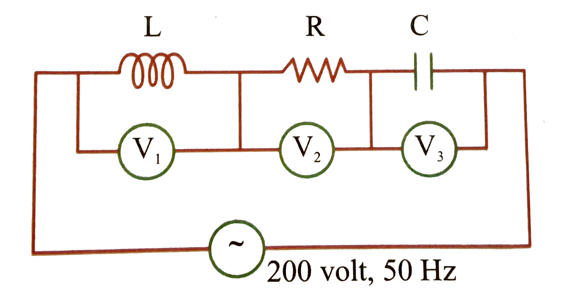
  3. If the readings V(1) and V(3) are 10. volt each, then reading of V(2) ...

    Text Solution

    |

  4. In a series LCR circuit as shown in figure, the heat developed in 80se...

    Text Solution

    |

  5. An eye can distinguish between two points of an object if they are sep...

    Text Solution

    |

  6. A Galilean telescope of 10-fold magnification has the length of 45 cm...

    Text Solution

    |

  7. The dispersive powers of two materials are 0.30 & 0.28. They are used ...

    Text Solution

    |

  8. Assume standard notations used for dispersion and deviation is a prise...

    Text Solution

    |

  9. In the figure shown a converging lens and a diverging lens of focal le...

    Text Solution

    |

  10. From the figure shown, establish a relation between mu1,mu2,and mu3

    Text Solution

    |

  11. Two point objects are placed on principal axis of thin converging lens...

    Text Solution

    |

  12. A ray of light (R(1)) is incident on a glass slab at an angle equal to...

    Text Solution

    |

  13. Assertion: A positively charged rod is held near a neutral conducting ...

    Text Solution

    |

  14. Assertion:A point charge q is placed near an arbitrary shaped solid co...

    Text Solution

    |

  15. Assetrion: If a proton and electron are placed in the same uniform ele...

    Text Solution

    |

  16. Assertion:- In a given situation of arrangement of charges, an extra c...

    Text Solution

    |

  17. Statement I: The curent density vecJ at any point in ohmic resistor ...

    Text Solution

    |

  18. Assertion:- To cells of unequal emf E(1) and E(2) having internal resi...

    Text Solution

    |

  19. Statement I : In the circuit in Fig. 7.46, both cells are ideal and of...

    Text Solution

    |

  20. Assertion:- Time constants of the cirucits shown in the figure are sam...

    Text Solution

    |