Home
Class 12
PHYSICS
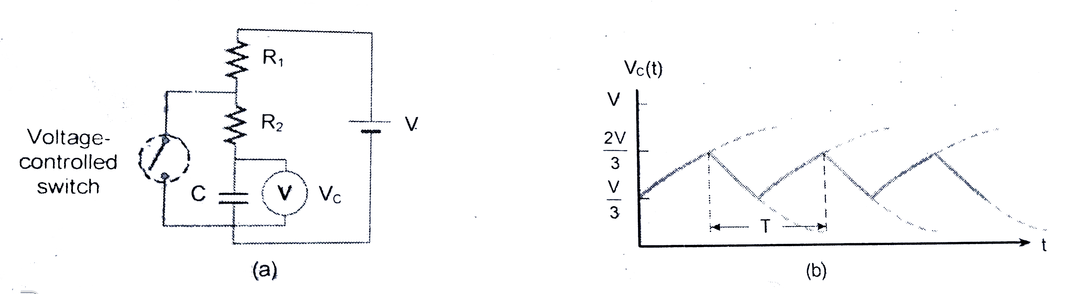
The switch in Figure (a) closes when Vc ...

The switch in Figure (a) closes when `Vc = 2V//3` and opens when `Vc = V//3`. The voltmeter reads a voltage as plotted in figure (b). What is the period T of the waveform? (take `R_(1) = 6R` and `R_(2) = 3R`, and `ln2 = 0.7` if required)
(a)

A

`12 RC`

B

`8.4 RC`

C

`11 RC`

D

none of these

Text Solution

Verified by Experts

The correct Answer is:
B

When the switch closes at `V_(c ) = 2 V//3` the capacitor discharges through `R_(2) = 3R`
T (discharge) `= 3RC ln 2` (since the voltage halves).
The charging occurs through `R_(1) + R_(2) = 9R`
T (charge) `= 9RC ln^(2)`
`T = 12 RC ln 2 ~~ 8.4 RC`
Promotional Banner

Similar Questions

Explore conceptually related problems

V_C is the ideal voltmeter in the figure. Resistance of the resistor shown is R. Initially the switch is in position 2 when charging of the capacitor starts. Initially the capacitor was uncharged. The switch in circuit shifts automatically from 2 to 1 when V_C gt 2V//3 and goes back to 2 from 1 when V_C lt V//3 . The ideal voltmeter reads voltage across capacitor as plotted. What is the period T of the wave from in terms of R and C ? ,

In the given figure, when temperature is increased then which of the following increases (A) R_(1) (B) R_(1) (C ) R_(2) -R_(1)

An ammeter A, a voltmeter V and a resistance R are connected as shown in the figure. If the voltmeter reading is 1.6V and the ammeter reading is 0.4 A, then R is

In the circuit shown, when switch S_(1) is closed and S_(2) is open, the ideal voltmeter shows a reaiding of 18 V . When switch S_(2) is closed and S_(1) is open, the reading of voltmeter is 24 V . When S_(1) and S_(2) both are closed, the voltmeter reading will be

In the given circuit , R_1 != R_2 and the reading of the voltmeter is the same, irrespective of whether the switch S is open or closed. Then, which of the following is correct?

The ammeter A reads 2A and the voltmeter V reads 20V, the value of resistance R is (Assuming finite resistance's of ammeter and voltmeter)

Let V and I respresent, respectively, the readings of the voltmeter and ammetre shows in Fig. 6.34 , and let R_(V) and R_(V) be their equivalent resistances. Because of the resistances of the meters, the resistnce R is not simply equal to V//I . (a) When the circuit is connected as shows in Fig. 6.34 (a), shows that R = (V)/(I) - R_(A) Explain why the true resistance R is always less than V//I . (b) When the connections are as shows in Fig. 6.34 (b) Show that R = (V)/(I - (V//R_(V))) Explain why the true resistance R is always greater than V//I . (c ) Show that the power delivered to the resistor in part (i) is IV - I^(2) R_(A) and that in part (ii) is IV - (V^(2)//R_(V))

In the circuit shown in figure, reading of voltmeter is V_1 when only S_1 is closed, reading of voltmeter is V_2 when only S_2 is closed, and reading of voltmeter is V_3 when both S_1 and S_2 are closed. Then .

A voltmeter of resistance 600 Omega when connected in turn across resistances R_(1) and R_(2) gives readings of V_(1) and V_(2) , respectively. If the battery is ideal, then

In the shown figures (1) and (2), capacitors are in steady state. Charging batteries are removed a switches S_(1) and S_(2) are closed at time t = 0 . The plot In I (I is the current in the resistor ) against time t the resitors R_(1) and R_(2) are shown in the figure. Choose the correct option (s) (1)