A

B

C

D
Text Solution
Verified by Experts
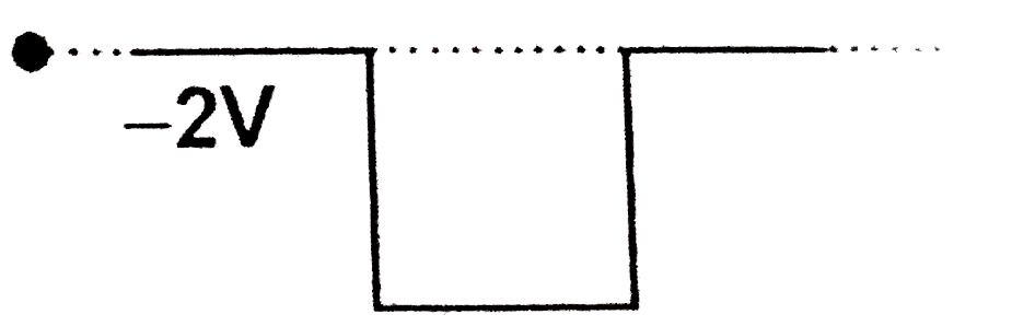
The correct Answer is:


Similar Questions
Explore conceptually related problems
Recommended Questions
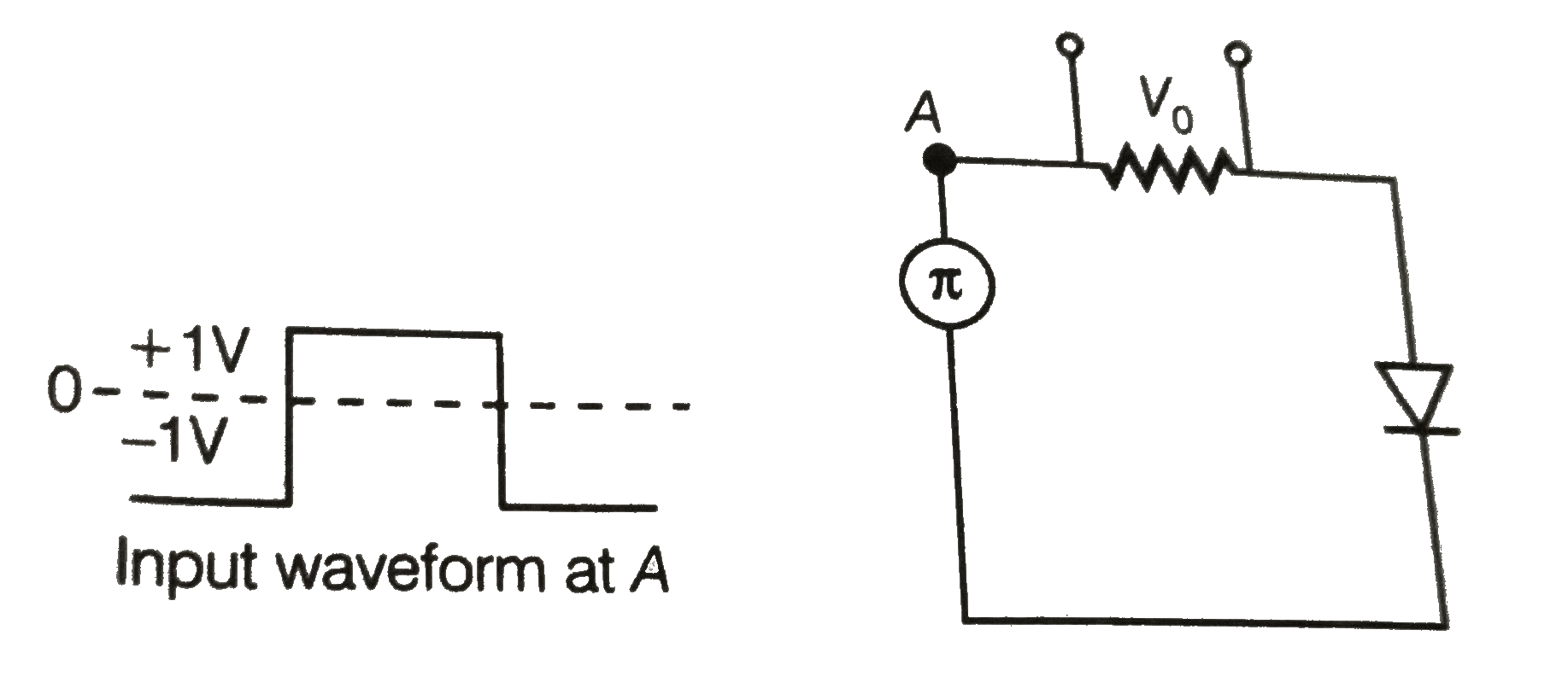
- Draw the output waveform across the resistor in the given figure.
Text Solution
|
- Draw and explain the output waveform across the load resistor R, if th...
Text Solution
|
- Draw the output waveform across the resistor (Fig.)
Text Solution
|
- Assuming the ideal diode, draw the output waveform for the circuit giv...
Text Solution
|
- What is an ideal diode ? Draw the output waveform across the load resi...
Text Solution
|
- Assuming the ideal diode, draw the output waveform for the circuit giv...
Text Solution
|
- प्रतिरोध के सिरों के बीच निर्गत तरंगरूप बनाइए|
Text Solution
|
- Draw the output waveform of a full wave rectifier.
Text Solution
|
- Draw the output wave form across the resistor
Text Solution
|