A
B
C
D
Text Solution
Verified by Experts
The correct Answer is:


Similar Questions
Explore conceptually related problems
Recommended Questions
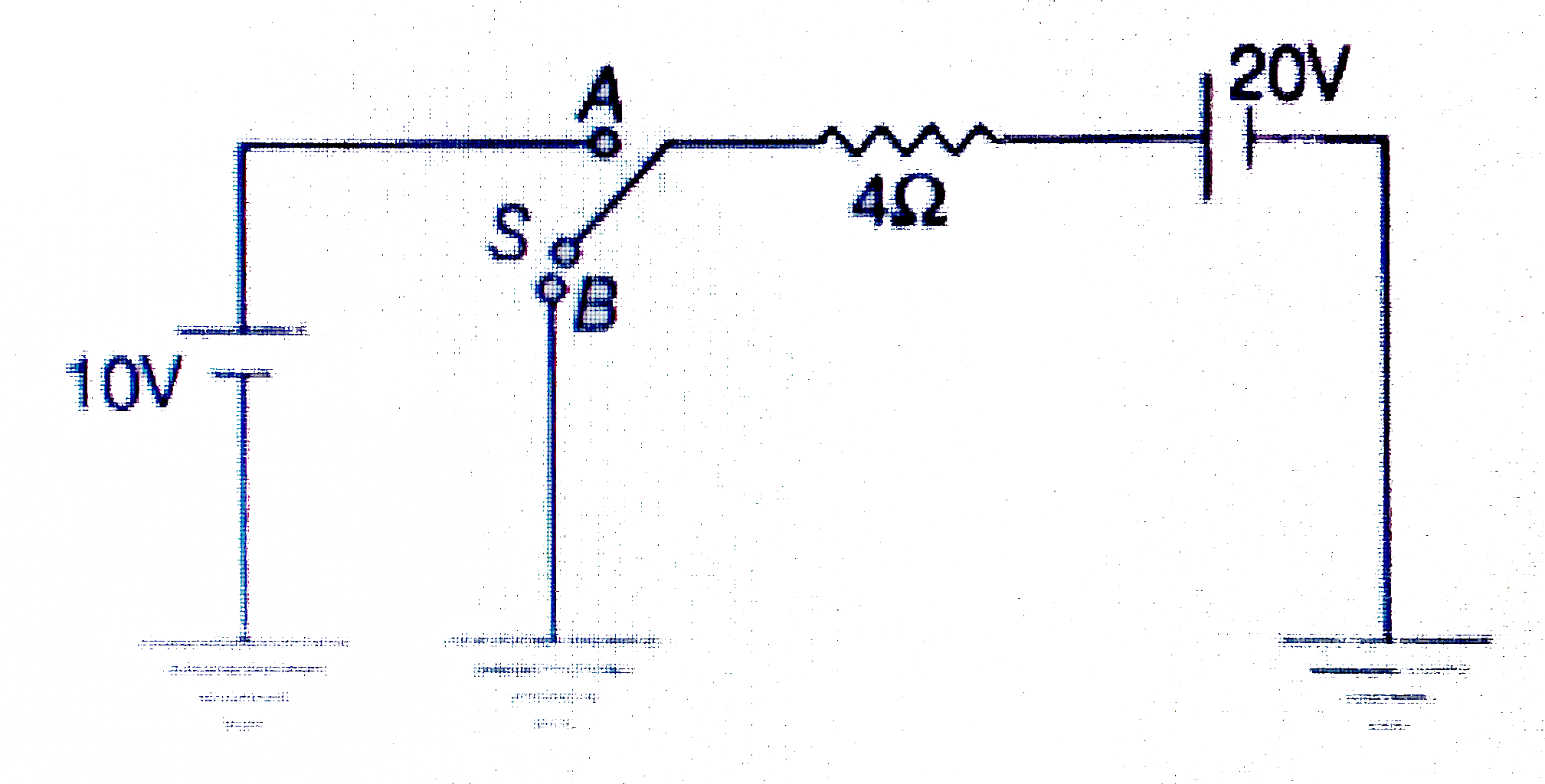
- In the circuit shown in figure switch S can be shift to position A or ...
Text Solution
|
- In the circuit shown in figure switch S is thrown to position 1 at t=0...
Text Solution
|
- In the circuit shown in the figure initialy the switch in position 1 f...
Text Solution
|
- In figure, the switch is in the position 1 for long time, then the swi...
Text Solution
|
- Condsider . In the circuit shown is the switch can be shifted to posit...
Text Solution
|
- In the circuit shown, initially the switch is in position 1 for a long...
Text Solution
|
- In the circuit shown below, the switch is in position 1 for a long tim...
Text Solution
|
- In the circuit shown in figure switch S can be shift to position A or ...
Text Solution
|
- In the given AC circuit, when switch S is at position 1, the source em...
Text Solution
|