A
B
C
D
Text Solution
Verified by Experts


Similar Questions
Explore conceptually related problems
Recommended Questions
- In the circuit shown in the figure, the ideal ammeter reading for curr...
Text Solution
|
- In the circuit shown all the ammeters are ideal. (a), If the switch S ...
Text Solution
|
- In the circuit shown in figure the reading of ammeter is the same with...
Text Solution
|
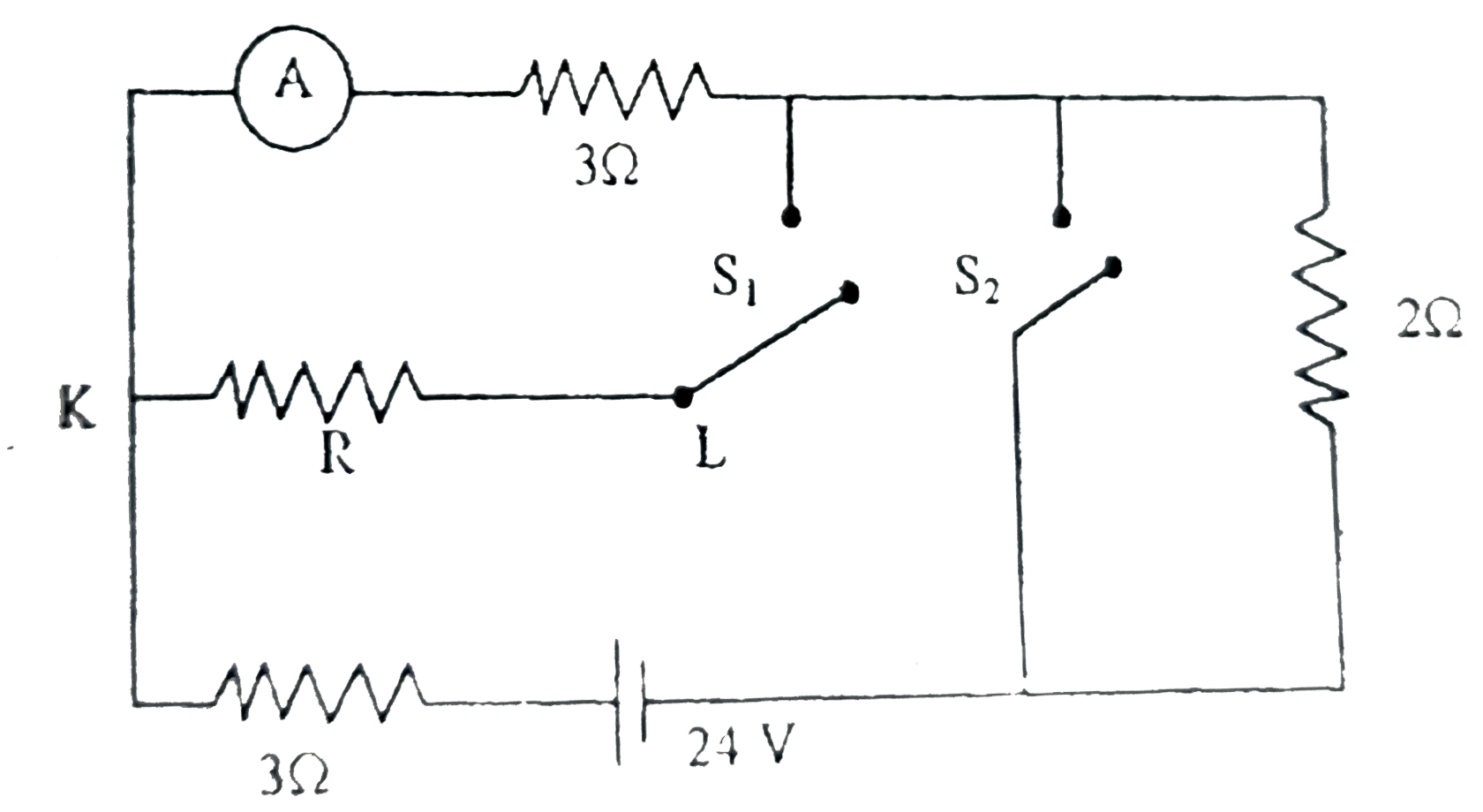
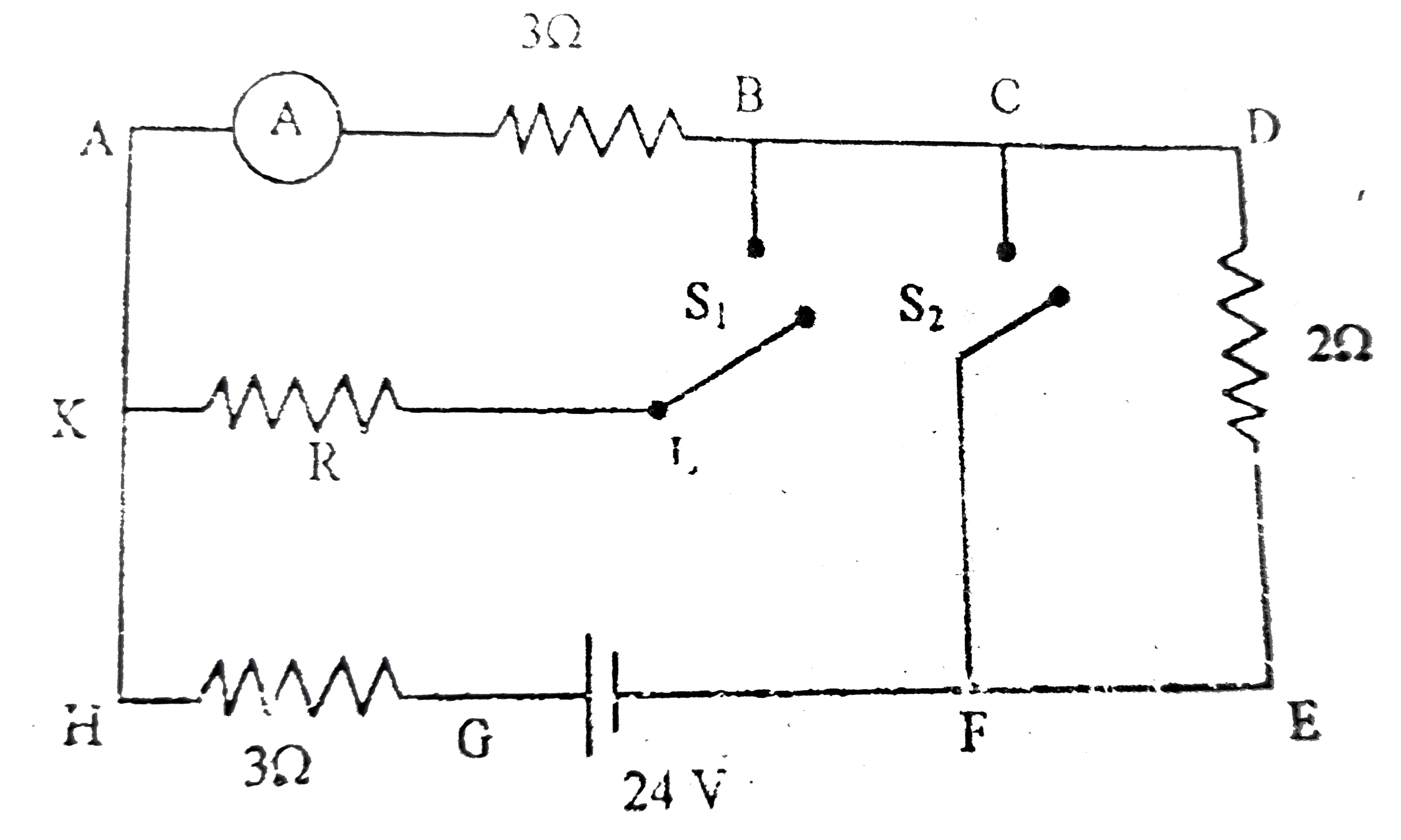
- In the given ciruit Ammeter reading is same when both switches S(1),S(...
Text Solution
|
- For the circuit shown, the ammeter reading is initially I. The switch ...
Text Solution
|
- In the circuit shown, the reading of ammeter when switch S is open ...
Text Solution
|
- In the circuit as shown in figure , the reading of ammeter (ideal) in ...
Text Solution
|
- In the circuit shown in Fig.4.20 both the ammeter and the cell have ne...
Text Solution
|
- In the circuit in figure, V is high resistance voltmeter and A is a lo...
Text Solution
|