Home
Class 12
PHYSICS
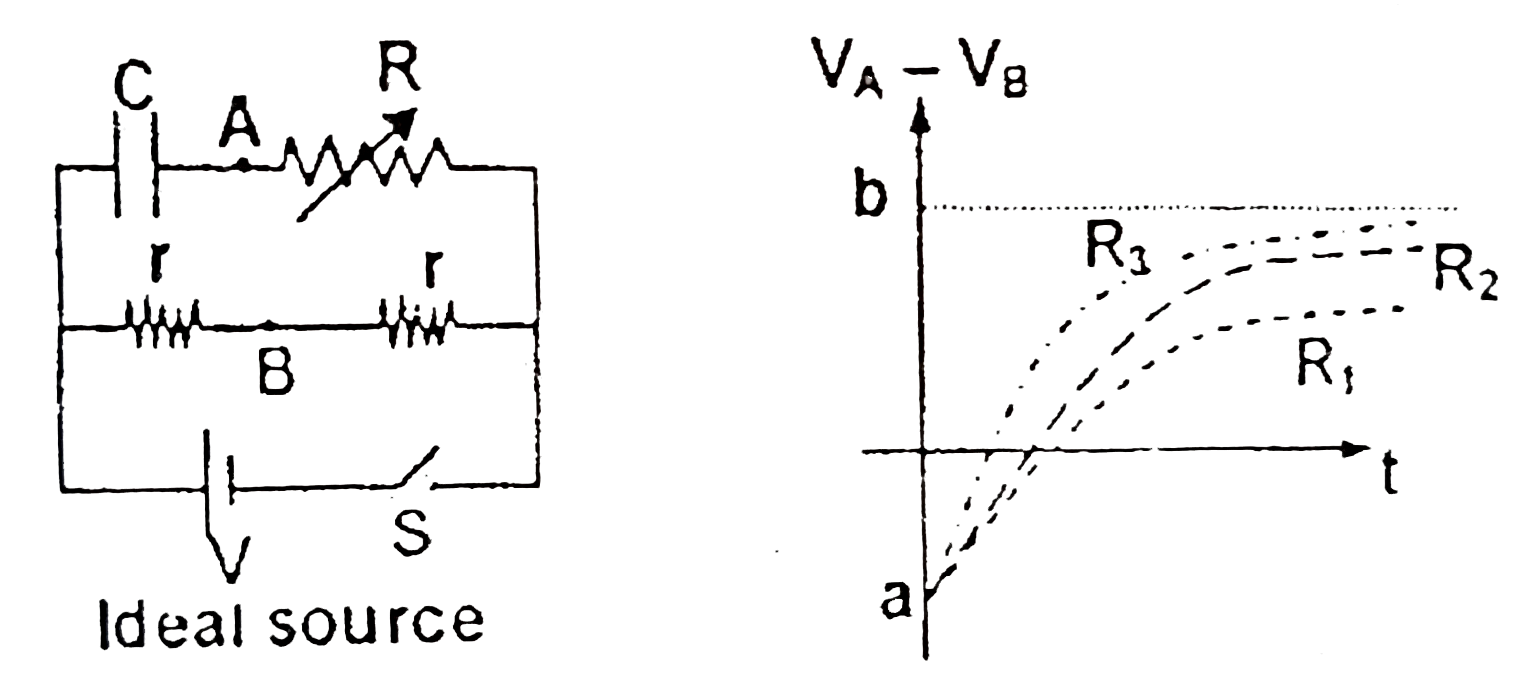
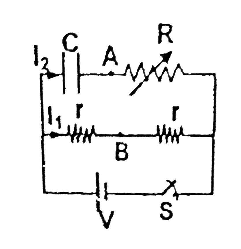
An uncharged capacitor C and a variable ...

An uncharged capacitor `C` and a variable resistance `R` are connected to an ideal source and two resistors with the help of a switch at `t=0` as shown in the figure. Initially capacitor is uncharged and switch `S` is closed at `t=0 sec`. The graph between `V_(A)-V_(B)` for variable Resistor `R` for its three different values `R_(1)`, `R_(2)`, and `R_(3)` versus time is shown in the figure `II`. Choose the correct statement

A

`R_(1) lt R_(2) lt R_(3)`

B

`R_(1) gt R_(2) gt R_(3)`

C

`|a| lt |b|`

D

`|a| gt |b|`

Text Solution

Verified by Experts

The correct Answer is:
b

Consider circuit at any time `t` after closing the switch :
`I_(1)=(V)/(2r)`, and `I_(2)=(V)/(R )e^(-(1)/(RC))`
`rArr V_(A)-V_(B)=RI_(2)-rI_(1)=Rxx(V)/(R )e^(-(1)/(RC))-rxx(V)/(2r)`
`rArr V_(A)-V_(B)=(-V)/(2)(1-2e^(-(1)/(RC)))`
`rArr a=(-V)/(2)`, and `v=(+V)/(2)`
When `V_(A)-V_(B)=0rArrt_(0)=RCln(2)`, Hence greater the `R`, greater the `t_(0)`
Promotional Banner

Similar Questions

Explore conceptually related problems

Find the potential difference between the points A and B (V_(A)-V_(B)) as shown in figure. (Initially all the capacitors are uncharged)

In the circuit shown in figure, the capacitor is charged with a cell of 5V .If the switch is closed at t=0 , then at t=12s , charge on the capacitor is

Three capacitors (of capacitances C , 2C and 3C ) and three resistors (of resistance R , 2R and 3R ) are connected with a battery and switch S as shown in the figure. When switch S is open, charges on the capacitors are shown. Switch S is closed at t=0 sec . The time constant of the circuit will be

An uncharged capacitor of capacitance C is connected with a battery of EMF V and a resistance R. The switch is closed at t=0 . The time instant at which the current in the circuit is (V)/(4R) is t=

In the shown figures (1) and (2), capacitors are in steady state. Charging batteries are removed a switches S_(1) and S_(2) are closed at time t = 0 . The plot In I (I is the current in the resistor ) against time t the resitors R_(1) and R_(2) are shown in the figure. Choose the correct option (s) (1)

An uncharged capacity ER C= 100muF with a resistor is connected with AC source as shown in the figure If R= is 50Omega and switch S is closed at t=0 maximum value of (v_(A)-V_B) is k volt. Calculate K

Consider the circuit shown. Switch is closed at t=0. Find the current through the battery as a function of time. Initially capacitor was uncharged.

An inductor of inductance L = 8 H and a resistor of resistance R = 2Ω are connected in series with a battery of emf E = 10 V as shown in the figure. If the switch is closed at t = 0, then the voltage drop across the inductor at t = 1 s will be in volts)

For ensuring dissipation of same energy in all three resistors (R_(1), R_(2), R_(3)) connected as shown in figure, their values must be related s

Two ideal batteries of emf V_1 and V_2 and three resistances R_1, R_2 and R_3 are connected as shown in the figure. The current in resistance R_2 would be zero if