Text Solution
Verified by Experts


Similar Questions
Explore conceptually related problems
Recommended Questions
- Charges q(1) , q(2) and q(3) are placed on capacitors of capacitance C...
Text Solution
|
- In plate A has 100 muC charge, while plate B has 60 muC charge. a. Whe...
Text Solution
|
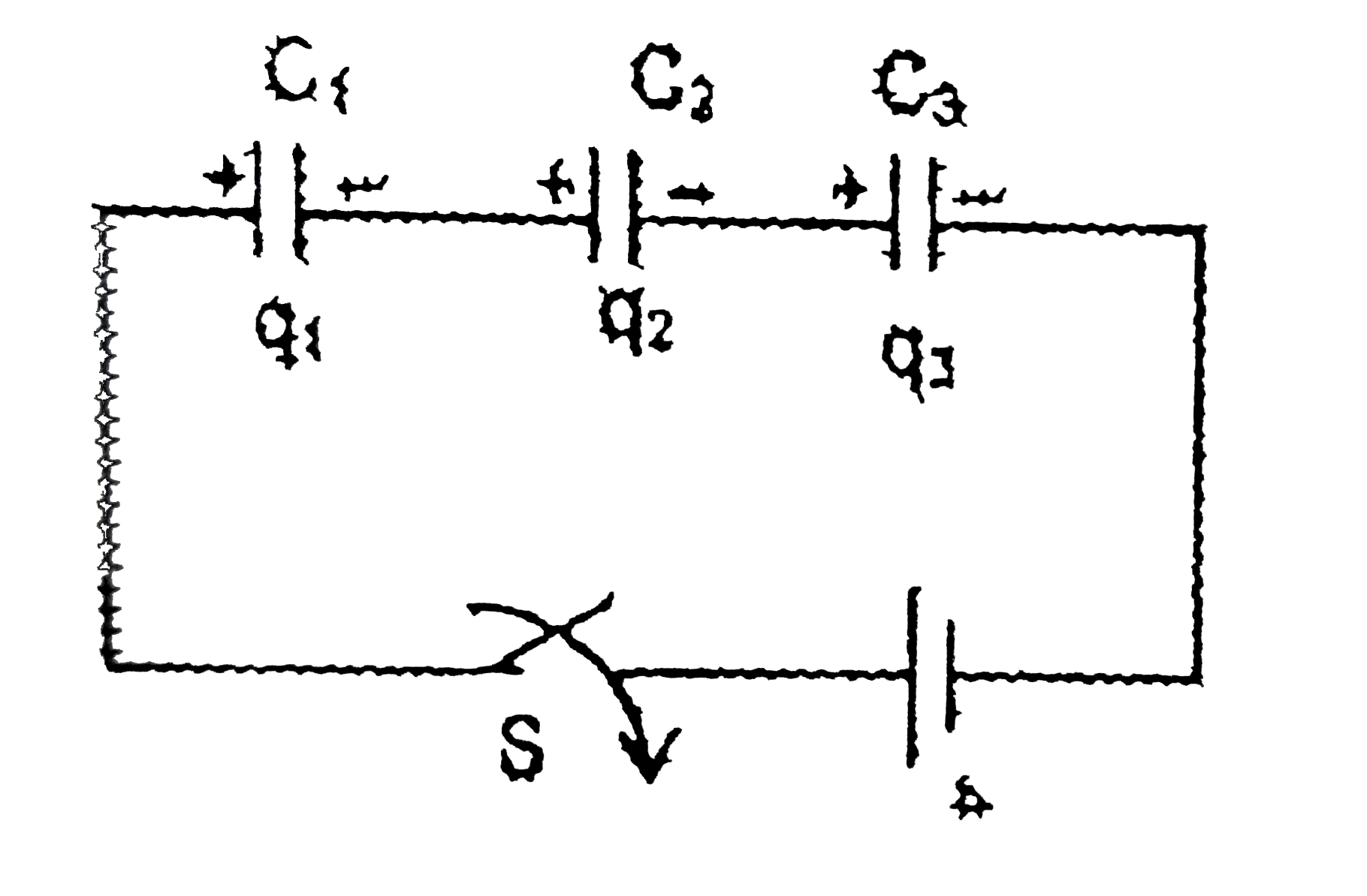
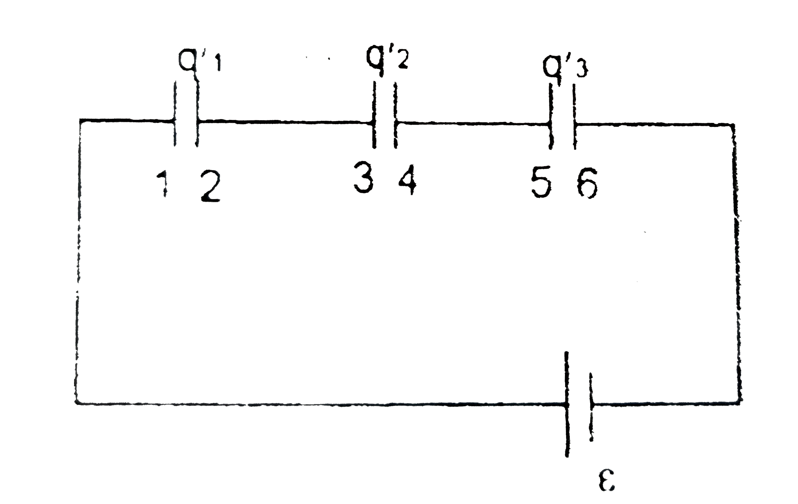
- In, the charges on C(1),C(2) , and C(3) , are Q(1), Q(2) , and Q(3) , ...
Text Solution
|
- Three capacitors are connected to D.C source of 100 volts shown in the...
Text Solution
|
- Four capacitors C(1)(=1 muF),C(2)(=2muF),C(3)(=3muF) and C(4)(=4 muF) ...
Text Solution
|
- Two capacitors of capacitances C(1) and C(2) are connected in parallel...
Text Solution
|
- Two capacitors of equal capacitance (C(1)=C(2)) are as shown in the fi...
Text Solution
|
- Two capacitor C(1) and C(2) , charged with charges q(1) and q(2) then ...
Text Solution
|
- The circle C(1) : x^(2)+y^(2)=3, with cenre at O, intersects the parab...
Text Solution
|