Text Solution
Verified by Experts


Similar Questions
Explore conceptually related problems
Recommended Questions
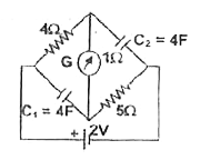
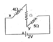
- In the circuit shown below the cell is ideal, with emf = 2 V: The resi...
Text Solution
|
- In the circuit shown in figure E,F, G and H are cell of emf 2,1,3, and...
Text Solution
|
- In the circuit the potential difference across the capacitor is 10 V ....
Text Solution
|
- In the circuit shown in fig. the cell is ideal with emf 15V. Each resi...
Text Solution
|
- In the circuit shows in Fig. 6.63, the cell is ideal with emf 9 V . If...
Text Solution
|
- In the given circuit , the potential difference across the capacitor i...
Text Solution
|
- In the shown circuit, all three capacitor are identical and have capac...
Text Solution
|
- In the circuit shown, the cell is ideal , with emf= 15 V. Ecah resista...
Text Solution
|
- In the circuit shown, the cell is ideal with emf = 2V . The resistance...
Text Solution
|