Home
Class 12
PHYSICS
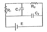
In the circuit shown in figure, R(1) = 1...

In the circuit shown in figure, `R(1) = 1Omega, R_(2) = 2Omega, C_(1) = 1 muF, C_(2) = 2 muF` and `E = 6 V`. Calculate charge on each capacitor in steady state

Text Solution

Verified by Experts

`q_(1)=2muC,q_(2)=12muC`
Promotional Banner

Similar Questions

Explore conceptually related problems

In the circuit shown in fig. R_(1) = 10 Omega, R_(2) = 5 Omega, C_(1) = 1 muF, C_(2) = 2muF, and E =6V. Calculate the charge on each capactor in the stedy state.

In the circuit shown below E_(1) = 4.0 V, R_(1) = 2 Omega, E_(2) = 6.0 V, R_(2) = 4 Omega and R_(3) = 2 Omega . The current I_(1) is

In the circuit shown C_(1) = 15 mu F, C_(2) == 30 muF , C_(3) = 30 muF , C_(4) = 30 muF and C_(5) = 60 muF . At steady state, the potential difference between points P and Q is 50 V. Calculate the potential difference across capacitor with capacitance C_(5)

In Fig, E =5 volt , r = 1 Omega, R_(2) = 4 Omega, R_(1) = R_(3) = 1 Omega and C = 3 muF . Then the numbercal value of the charge on each plate of the capacitor is

In the circuit shown in figure R_(1)=R_(2)=10Omega, E_(1)=20V, E_(2)=40V . For what value of R, the thermal power developed in it will be maximum (in Omega )?

In the given circuit, R_(1) = 10Omega R_(2) = 6Omega and E = 10V, then correct statement is

In the circuit shown , the batteries have emf E_1 = E_2= 1V , E_3 = 2.5 V, and the resistance R_1 = 10Omega, R_2 = 20 Omega , Capacitance C = 10 muF . The charge on the left plate of the charge on the left plate of the capacitor C at steady state is

Four capacitors C_(1)=8 muF , C_(2)=2 muf, C_(3)=6 muF , and C_(4)=6, muF are arranged as shown in. Find the charge on all the capacitors in the circuit. .

In the given circuit. E_(1) = 6 volts, E_(2) = 2 volts, E_(3) = 6 volts R_(1) = 6OmegaR_( 2)=2Omega R_(3) = 4Oemga, R_(4) = 3Omega and C=5muF . Find the current in R_(3) and energy stored in the capacitor at steady state

The circuit consists of two resistors (of resistance R_(1) = 20 Omega and R_(2) = 10 Omega ), a capacitor (of capacitance C =10 muF ) and two ideal cells. In the circuit shown the capacitor is in steady state and the switch S is open The current through the resistor R_(2) just after the switch S is closed is :