Home
Class 12
PHYSICS
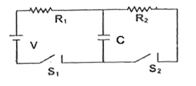
A battery of emf V volts, resistances R(...

A battery of emf V volts, resistances `R_(1)` and `R_(2)`, a condenser C and switches S1, and S2, are connected in a circuit as shown. The capacitor C gets fully charged to V volts when

A

`S_(1)` and `S_(2)` are both closed

B

`S_(1)` and `S_(2)` are both open

C

`S_(1)` closed and `S_(2)` is open

D

`S_(1)` open and `S_(2)` is closed

Text Solution

Verified by Experts

The correct Answer is:
C
Promotional Banner

Similar Questions

Explore conceptually related problems

Two batteries of emf E_(1) and E_(2) , a capacitor of capacitance I 'C' and a resistor R are connected in a circuit as shown When the switch S is shifted from position (1) to (2), then Esta the charge flow and work done by battery E_(2)

In the circuit, a battery of emf E, a resistance R and inductance coil L_(1) and L_(2) and switch S are connected as shown. In Fig. Initially the switch is open

Two capacitors C_(1) and C_(2) are connected with two batteries of emf epsilon_(1) and epsilon_(2) . The circuit components are connected with a switch S as shown in. Initially the switch is open and the capacitors are charged. Find the heat produced when switch S is closed. .

The circuit consists of two resistors (of resistance R_(1) = 20 Omega and R_(2) = 10 Omega ), a capacitor (of capacitance C =10 muF ) and two ideal cells. In the circuit shown the capacitor is in steady state and the switch S is open The charge on capacitor in steady state with switch S closed.

The circuit consists of two resistors (of resistance R_(1) = 20 Omega and R_(2) = 10 Omega ), a capacitor (of capacitance C =10 muF ) and two ideal cells. In the circuit shown the capacitor is in steady state and the switch S is open The current through the resistor R_(2) just after the switch S is closed is :

The circuit consists of two resistors (of resistance R_(1) = 20 Omega and R_(2) = 10 Omega ), a capacitor (of capacitance C =10 muF ) and two ideal cells. In the circuit shown the capacitor is in steady state and the switch S is open the circuit is in steady state with switch S closed. Now the switch S is opened. Just after the switch S is opened. the current through resistance R_(1) is

A battery of emf 2 V and initial resistance 1 Omega is connected across terminals A and B of the circuit shown in figure .

In the given circuit the capacitor (C) may be charged through resistance R by a battery V by closing switch (S_1) . Also when (S_1) is opend and (S_2) is closed the capacitor is connected in series with inductor (L). When the capacitor gets charged compleely, (= (S_1) is opened and (S_2) is closed, Then,

An uncharged capacitor C , Resistances R_(1)=R and R_(2)=2R , cells of emf epsilon_(1)=epsilon and epsilon_(2)=epsilon are connected as shown in the figure. Switch S is initially connected to terminal 1 for a long time and then it is connected to terminal 2 for an another long duration. IF H_(1) , U_(1) are the heat energies lost through the resistor R_(1) and energy stored in the capacitor respectively at steady state, when the switch is connected to terminal 1 and H_(2) , U_(2) are corresponding value when the switch is connected to terminal 2 . Choose the correct statements(s).

The capacitor C_1 in the flgure shown initially carries a charge q_0 . When the switches S_1 and S_2 are closed,capacitor C_1 is connected in series to a resistor R and a second capacitor C_2 which is initially uncharged. the total heat dissipated in the circuit during the discharging process of C_1 is