A
B
C
D
Text Solution
Verified by Experts
The correct Answer is:


Similar Questions
Explore conceptually related problems
Recommended Questions
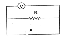
- For the circuit shown in figure when R = 2Omega, V=0.75 volts, when R=...
Text Solution
|
- In the circuit diagram of zener diode as shown in figure, when the val...
Text Solution
|
- Does the current in an A.C. circuit lag, lead or remain in phase with ...
Text Solution
|
- Consider the circuit shown in the figure, the cell is ideal. The readi...
Text Solution
|
- For a triode, at V(g)=-1 volt, the following observations were taken V...
Text Solution
|
- A current of 2 A flows in an electric circuit as shown in figure. The ...
Text Solution
|
- V वोल्ट से त्वरित होकर इलेक्ट्रॉन v चाल से एक लक्ष्य से टकराता है ...
Text Solution
|
- दिये गये परिपथ में वोल्ट मीटर V(1)" और "V(2) में से प्रत्येक का पाठ्या...
Text Solution
|
- एक सिलिकॉन डायोड के लिए V-I अभिलाक्षणिक वक्र चित्र में प्रदर्शित है| ड...
Text Solution
|