A
B
C
D
Text Solution
Verified by Experts
The correct Answer is:


Similar Questions
Explore conceptually related problems
Recommended Questions
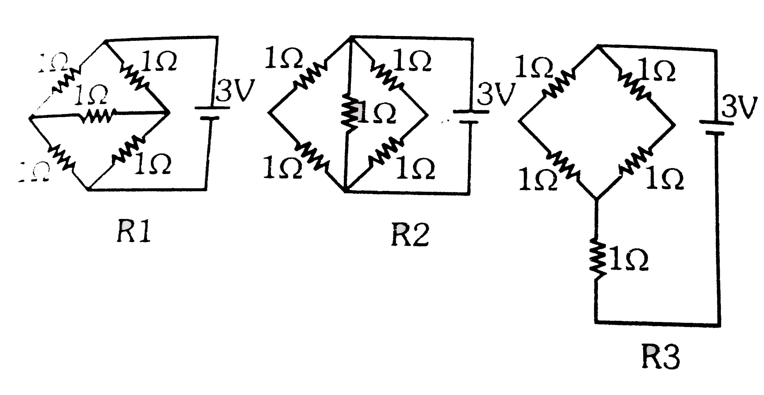
- Figure shows three resistor configurations R1,R2 and R3 connected to 3...
Text Solution
|
- Figure shows three resistor configurations R1,R2 and R3 connected to 3...
Text Solution
|
- ln a triangle with sides a, b, c if r1 gt r2 gt r3 (which are the ex-r...
Text Solution
|
- R1 = R2 = R3 = R4 = 2ohm. Find voltage across capacitor at steady stat...
Text Solution
|
- The radii r1,r2,r3 of enscribed circles of triangle ABC are in HP . If...
Text Solution
|
- R1 = R2 = R3 = R4 = 2ohm. Find voltage across capacitor at steady stat...
Text Solution
|
- What is the phenotype of wheat kernal colour for the genotype: R1 R1 r...
Text Solution
|
- Formulae OF inradius(r)||ex-radius(r1,r2,r3)
Text Solution
|
- Problem Base on Inradius (r) and Ex-Radius (R1,R2,R3)||The Ambiguous C...
Text Solution
|