A
B
C
D
Text Solution
Verified by Experts
The correct Answer is:


Similar Questions
Explore conceptually related problems
Recommended Questions
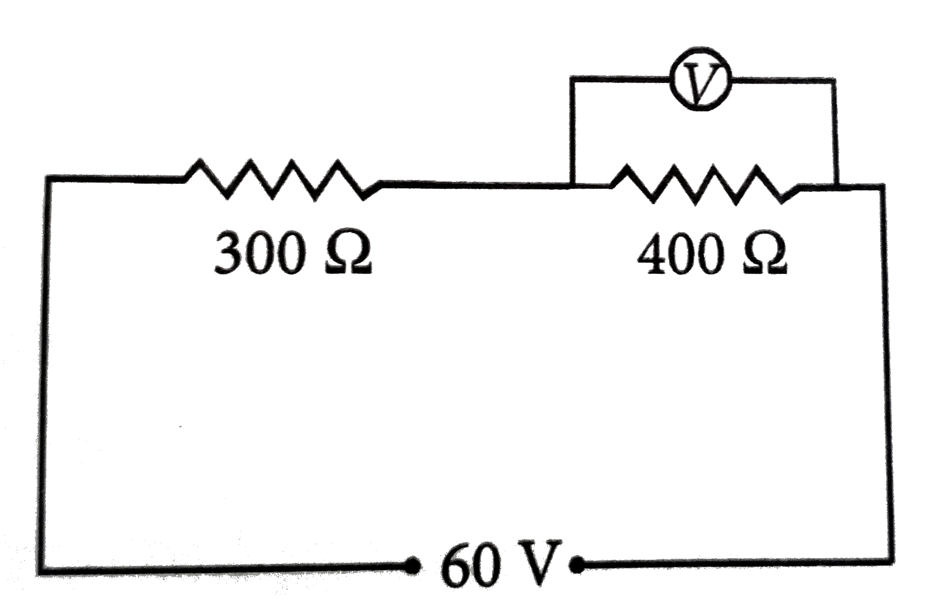
- In the circuit shown in figure, a voltmeter reads 30 volts when it is ...
Text Solution
|
- State ohm's law. In the circuit shown in figure, a voltmeter reads 30 ...
Text Solution
|
- In the circuit, a voltmeter reads 30 V when it is connected across 400...
Text Solution
|
- Shown two ideal voltmeters and an ammeter, which are connected across ...
Text Solution
|
- In the circuit shows in Fig. 6.22, a voltmeter reads 30 V when it is c...
Text Solution
|
- In the circuit given below, a voltmeter reads 20V when it is connected...
Text Solution
|
- In the circuit shown, when a voltmeter is connected across any one of ...
Text Solution
|
- In the circuit shown in figure-3 .3 89, the voltmeter reads 30V when i...
Text Solution
|
- In the circuit diagram shown in Fig. 4.53, a voltmeter reads 30 V when...
Text Solution
|