Home
Class 10
PHYSICS
In an experiment to determine equivalent...

In an experiment to determine equivalent resistance of two resistors `R_1` and `R_2` in series, which one of the following circuit diagrams shows the correct way of connecting the voltmetr in the circuit?

A

I

B

II

C

III

D

IV

Text Solution

Verified by Experts

Promotional Banner

Topper's Solved these Questions

  • ELECTRICITY

    MODERN PUBLICATION|Exercise EXERCISE|303 Videos
  • MAGNETIC EFFECTS OF ELECTRIC CURRENT

    MODERN PUBLICATION|Exercise EXERCISE|265 Videos

Similar Questions

Explore conceptually related problems

In an experiment to find the equivalent resistnce of two resistors connected in series, four circuits were set up as shown The voltmeter has been correctly connected in the arrangement

A student set up electric circuit shown here for finding the equivalent resistance of two resistors in series. In this circuit

Find the equivalent resistance of three resistors of 2Ohm,3Ohm,4Ohm when connected in series ?

Which of the circuit components in the following circuit diagram are connected inparallel?

In the circuit given ahead, the resistors R_1 and R_2 are connected

The circuit diagram shown below is used to find the effective resistqnec of two resistors in series.which circuit diagram represents correctly

Consider the following circuit: R_1=R_2=R_3=R_4=R_5=2ohm What current will flow in the circuit?

Two students perform the experiments on series and parallel combinatins of two given resistors R_1 and R_2 and plotted the following V-I graphs: Which of the graph is correctly labelled in term sof the words "series" and "paralle"? justify your answer.

Equivalent resistance of three resistros each of resistance of 2 ohm connected in series as determined experimentally should her

MODERN PUBLICATION-ELECTRICITY-EXERCISE
  1. The current flowing through a conductor and the potential difference a...

    Text Solution

    |

  2. The following instruments are availabel in a laboratory Miliammeter A1...

    Text Solution

    |

  3. In an experiment to determine equivalent resistance of two resistors R...

    Text Solution

    |

  4. The rest positions of the needles in a milliammeter and voltmeter when...

    Text Solution

    |

  5. The only correct statement for the two circuits X and Y shown below:

    Text Solution

    |

  6. The only correct statement for the following circuit is

    Text Solution

    |

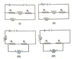
  7. Three students (A),(B) and ( C) connected their two resistor R1 and R2...

    Text Solution

    |

  8. To study the dependence of current on the potential difference across ...

    Text Solution

    |

  9. While performing the experiment to study the dependence of current on ...

    Text Solution

    |

  10. In an experiment to determine equivalent resistance of two resistors R...

    Text Solution

    |

  11. A 6 V battery for internal resistance 2 ohm is connected across a 10 o...

    Text Solution

    |

  12. A student set up his for finding the equivalent resistance of a seris ...

    Text Solution

    |

  13. Complete the prime factor tree :

    Text Solution

    |

  14. An ammeter and a voltmeter are joined in series to a cell. Their readi...

    Text Solution

    |

  15. The number of division in ammeter of range 2A is 10 and voltmeter of r...

    Text Solution

    |

  16. Ohms law experiment is performed seperately with individual resistors ...

    Text Solution

    |

  17. In Ohm's law experiment the physicla quantity quantities which is are ...

    Text Solution

    |

  18. The graph between current and the potential diference in the experimen...

    Text Solution

    |

  19. The circuit diagram shown below is used to find the effective resistqn...

    Text Solution

    |

  20. A student set up electric circuit shown here for finding the equivalen...

    Text Solution

    |