Home
Class 10
PHYSICS
A student set up electric circuit shown ...

A student set up electric circuit shown here for finding the equivalent resistance of two resistors in series. In this circuit

A

resistors are correctly connected but voltmeter is wrongly connected.

B

resistors are correctly connected but ammeter is wrongly connected.

C

resistors as well as voltmeter are wrongly connected.

D

resistors as well as ammeter are wrongly connected.​

Text Solution

Verified by Experts

Promotional Banner

Topper's Solved these Questions

  • ELECTRICITY

    MODERN PUBLICATION|Exercise EXERCISE|303 Videos
  • MAGNETIC EFFECTS OF ELECTRIC CURRENT

    MODERN PUBLICATION|Exercise EXERCISE|265 Videos

Similar Questions

Explore conceptually related problems

Find the equivalent resistance between point A and B in the circuit.

A bridge circuit is shown in the figure. The equivalent resistance between points A and B is

The circuit diagram shown below is used to find the effective resistqnec of two resistors in series.which circuit diagram represents correctly

In an experiment to determine equivalent resistance of two resistors R_1 and R_2 in series, which one of the following circuit diagrams shows the correct way of connecting the voltmetr in the circuit?

The equivalent resistance between A and B of the given figure circuit is

Find the equivalent of resistances of the individual resistance connected in series?

In an experiment to find the equivalent resistnce of two resistors connected in series, four circuits were set up as shown The voltmeter has been correctly connected in the arrangement

A circuit is shown in the diagram Find the value of R.

Find out the following in the electric circuit given in figure. Effective resistance of two 8 ohm resistors in the combination?

MODERN PUBLICATION-ELECTRICITY-EXERCISE
  1. The graph between current and the potential diference in the experimen...

    Text Solution

    |

  2. The circuit diagram shown below is used to find the effective resistqn...

    Text Solution

    |

  3. A student set up electric circuit shown here for finding the equivalen...

    Text Solution

    |

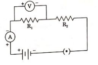
  4. In the circuit given ahead, the resistors R1 and R2 are connected

    Text Solution

    |

  5. Identify the circuit in which the electrical components have been prop...

    Text Solution

    |

  6. 4 students plotted the graph showing dependence of current I on potent...

    Text Solution

    |

  7. Define one watt hour.

    Text Solution

    |

  8. A cylinder of a material is 10 cm long and has a cross section of 2 cm...

    Text Solution

    |

  9. Explain the following : Why is the tungsten used almost exclusively fo...

    Text Solution

    |

  10. A resistance of 10 ohm is bent in the form of a closed circle. What is...

    Text Solution

    |

  11. Why is much less heat generated in long electric cables than in filame...

    Text Solution

    |

  12. State which has a higher resistance a 50 W or a 25 w lamp bulb and how...

    Text Solution

    |

  13. Pick out conductors and insulators from the following Metals, Glass, R...

    Text Solution

    |

  14. Pick out conductors and insulators from the following Metals, Glass, R...

    Text Solution

    |

  15. Pick out conductors and insulators from the following Metals, Glass, R...

    Text Solution

    |

  16. Pick out conductors and insulators from the following Metals, Glass, R...

    Text Solution

    |

  17. Pick out conductors and insulators from the following Metals, Glass, R...

    Text Solution

    |

  18. Pick out conductors and insulators from the following Metals, Glass, R...

    Text Solution

    |

  19. Name a source of emf.

    Text Solution

    |

  20. What is SI unit of electric potential?

    Text Solution

    |