Home
Class 12
PHYSICS
Figure shows a part of an electric circu...

Figure shows a part of an electric circuit.The potentials at the points a,b and c are 30V,12V and 2V respectively.Find the currents through the three resistors.

Promotional Banner

Topper's Solved these Questions

  • ELECTRICAL MEASUREMENTS

    MODERN PUBLICATION|Exercise EXERCISE|44 Videos
  • ELECTRIC POTENTIAL

    MODERN PUBLICATION|Exercise EXERCISE|38 Videos
  • ELECTROMAGNETIC INDUCTION

    MODERN PUBLICATION|Exercise EXERCISE|146 Videos

Similar Questions

Explore conceptually related problems

A voltage of 60 V is applied across a carbon resistor with first, second and third rings of orange, black and blue colours respectively. Find the value of current through the resistor?

A voltage of 30 V is applied across certain carbon resistor with first, second and third rings of blue, black and yellow colours respectively. Find the value of current through the resistance.

A voltage of 30 V is applied across a carbon resistor with first, second and third rings of blue, black and yellow colours respectvely. Calculate the value of current, in mA through the resistor.

In a series LCR circuit the voltage across an inductor, a capacitor and a resistor are 30V, 30V and 60V respectively. What is the phase difference between the applied voltage and current in the circuit?

A series LCR circuit is connected to an a.c. source 220 V - 50 Hz as shown in fig. If the reading of the three voltemeters V_(1), V_(2), V_(3) are 65 V, 415 V and 204 V respectively. Calculate current in the circuit.

In a series LCR circuit the voltage across an inductor, a capacitor and a resistor are 20V, 20V and 40V respectively. What is the phase difference between the applied voltage and the current in the circuit?

Find out the following in the electric circuit given in figure. Current flowing through 4 ohm resistors?

E^@ of three metals A, B, C are -1.4 V, + 0.6V, - 3.4V respectively. The reducing power of these metals are in order :

Find out the magntude of resistance X in the circuit shown in the figure, when no current flows through the 5Omega resistor.

MODERN PUBLICATION-ELECTRICAL MEASUREMENTS-EXERCISE
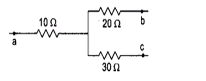
  1. Figure shows a part of an electric circuit.The potentials at the point...

    Text Solution

    |

  2. State and explain Kirchhoff's laws.

    Text Solution

    |

  3. State and explain Kirchhoff's laws.

    Text Solution

    |

  4. State and explain Kirchhoff's laws.

    Text Solution

    |

  5. Derieve condition of a balanced wheatstone's bridge.

    Text Solution

    |

  6. Using Kirchoff's law, derive the condition for the balance of a Wheats...

    Text Solution

    |

  7. Using Kirchoff's law, derive the condition for the balance of a Wheats...

    Text Solution

    |

  8. State Wheatstone bridge principle. Use kirchoff'slaws to obtain the re...

    Text Solution

    |

  9. State Wheatstone bridge principle. Use kirchoff'slaws to obtain the re...

    Text Solution

    |

  10. Draw the circuit diagram of Wheatstone bridge. Under what condtion, no...

    Text Solution

    |

  11. Draw the circuit diagram of Wheatstone bridge. Under what condtion, no...

    Text Solution

    |

  12. With help of circuit diagram, explain how a meter bridge can be used t...

    Text Solution

    |

  13. Explain the principle of Wheatstone bridge for determining and unknown...

    Text Solution

    |

  14. What is a slide wire bridge? How can you find unknown resistance by it...

    Text Solution

    |

  15. With help of circuit diagram, explain how a meter bridge can be used t...

    Text Solution

    |

  16. Draw a circuit diagram for determining the unknown resistance R using ...

    Text Solution

    |

  17. Draw a circuit diagram of a meter bridge and write the necessary mathe...

    Text Solution

    |

  18. Draw a cricuit diagram of a metre bridge arranged to find the value of...

    Text Solution

    |

  19. Draw a cricuit diagram of a metre bridge arranged to find the value of...

    Text Solution

    |

  20. Draw a neatly labelled diagram of a potentionmeter and explain its pri...

    Text Solution

    |

  21. Explain the principle on which the working of a potentiometer is based...

    Text Solution

    |