Home
Class 12
PHYSICS
Figure shows a series LCR circuit connec...

Figure shows a series LCR circuit connected to a variable frequency 230 V source. L = 5.0 H, `C = 80 muF`, `R= 40 Omega` . Obtain the impedance of the circuit and the amplitude of current at the resonating frequency. :

Promotional Banner

Topper's Solved these Questions

  • ALTERNATING CURRENTS

    MODERN PUBLICATION|Exercise EXERCISE|201 Videos
  • CAPACITOR

    MODERN PUBLICATION|Exercise EXAMPLE|262 Videos

Similar Questions

Explore conceptually related problems

Figure 7.21 shows a series LCR circuit connected to a variable frequency 230 V source. L = 5.0 H, C = 80 muF , R= 40 Omega . Determine the source frequency which drives the circuit in resonance. :

The given circuit diagram shows a series LCR circuit connected to a variable frequency 230 V source. Obtain the impedacne of the circuit and the amplitude of current at resonating frequency.

Figure shows a series LCR circuit connected to a variable frequency 230 V source. L = 5.0 H, C = 80 muF , R= 40 Omega . Determine the rms potential drops across the three elements of the circuit. Show that the potential drop across the LC combination is zero at the resonating frequency. :

The given circuit diagram shows a series LCR circuit connected to a variable frequency 230 V source. Determine the source frequency which drives the circuit in resonance.

The given circuit diagram shows a series LCR circuit connected to a variable frequency 230 V source. Determine the RMS potential drops across the three elements of the circuit.

The given circuit diagram shows a series LCR circuit connected to a variable frequency 230 V source. How do you explain the observations that the algebraic sum of the voltages across the three elements is greater than the supplied voltages?

LCR circuit connected to a variable frequency 230 V source . L=5.0 H, C=80 micro F and R=40 ohm. Keeping the source frequency equal to the resonating frequency of the series LCR circuit, if the three elements, L, C and R are arranged in parallel, show that the total current in the parallel LCR circuit is minimum at this frequency. Obtain the current rms value in each branch of the circuit for the elements and source.

MODERN PUBLICATION-ALTERNATING CURRENTS-EXERCISE
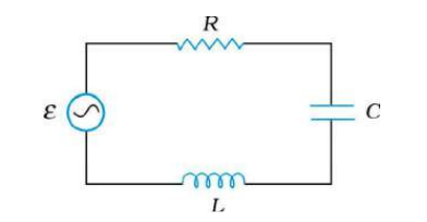
  1. Figure shows a series LCR circuit connected to a variable frequency 23...

    Text Solution

    |

  2. A lamp is connected in series with a capacitor to a high frequency a.c...

    Text Solution

    |

  3. An air core coil and an electric bulb are connected in series across a...

    Text Solution

    |

  4. Answer the following questions: A choke coil in series with a lamp is ...

    Text Solution

    |

  5. A lamp is connected in series with a capacitor. What will happen if d....

    Text Solution

    |

  6. Explain : voltages across L and C in series are 180^(@) out of phase, ...

    Text Solution

    |

  7. The total impedance of a circuit decreases, when a capacitor is added ...

    Text Solution

    |

  8. When an a.. Circuit with a series combination of inductance, capacitan...

    Text Solution

    |

  9. When a capacitor is connected in series LR circuit the alternating cur...

    Text Solution

    |

  10. An alternating voltage of frequency f is applied across LCR circuit. L...

    Text Solution

    |

  11. An alternating voltage of frequency f is applied across LCR circuit. L...

    Text Solution

    |

  12. Give applications of resonance in series LCR circuit.

    Text Solution

    |

  13. An capacitor C, a variable resistor R and a bulb B are connected in se...

    Text Solution

    |

  14. An capacitor C, a variable resistor R and a bulb B are connected in se...

    Text Solution

    |

  15. A capacitor with capacitance C and a coil with active resistance R and...

    Text Solution

    |

  16. An inductor L of inductance X(L) is connected in series with a bulb B ...

    Text Solution

    |

  17. An inductor L of inductance X(L) is connected in series with a bulb B ...

    Text Solution

    |

  18. As shown in figure an electric lamp having coil of negligible inductan...

    Text Solution

    |

  19. As shown in figure an electric lamp having coil of negligible inductan...

    Text Solution

    |

  20. In the circuit shown below R represents an electric bulb. If the frequ...

    Text Solution

    |

  21. Show in the figure, two electric circuits A and B. Calculate the ratio...

    Text Solution

    |