Home
Class 12
PHYSICS
Figure shows a series LCR circuit connec...

Figure shows a series LCR circuit connected to a variable frequency 230 V source. L = 5.0 H, `C = 80 muF`, `R= 40 Omega` . Obtain the impedance of the circuit and the amplitude of current at the resonating frequency. :

Promotional Banner

Topper's Solved these Questions

  • TEXTUAL QUESTIONS

    MODERN PUBLICATION|Exercise EXERCISE|507 Videos
  • STRUCTURE OF NUCLEUS

    MODERN PUBLICATION|Exercise EXERCISE|47 Videos
  • TEXUAL QUESTIONS

    MODERN PUBLICATION|Exercise EXERCISE|195 Videos

Similar Questions

Explore conceptually related problems

Figure 7.21 shows a series LCR circuit connected to a variable frequency 230 V source. L = 5.0 H, C = 80 muF , R= 40 Omega . Determine the source frequency which drives the circuit in resonance. :

The given circuit diagram shows a series LCR circuit connected to a variable frequency 230 V source. Obtain the impedacne of the circuit and the amplitude of current at resonating frequency.

Figure shows a series LCR circuit connected to a variable frequency 230 V source. L = 5.0 H, C = 80 muF , R= 40 Omega . Determine the rms potential drops across the three elements of the circuit. Show that the potential drop across the LC combination is zero at the resonating frequency. :

The given circuit diagram shows a series LCR circuit connected to a variable frequency 230 V source. Determine the source frequency which drives the circuit in resonance.

The given circuit diagram shows a series LCR circuit connected to a variable frequency 230 V source. Determine the RMS potential drops across the three elements of the circuit.

The given circuit diagram shows a series LCR circuit connected to a variable frequency 230 V source. How do you explain the observations that the algebraic sum of the voltages across the three elements is greater than the supplied voltages?

LCR circuit connected to a variable frequency 230 V source . L=5.0 H, C=80 micro F and R=40 ohm. Keeping the source frequency equal to the resonating frequency of the series LCR circuit, if the three elements, L, C and R are arranged in parallel, show that the total current in the parallel LCR circuit is minimum at this frequency. Obtain the current rms value in each branch of the circuit for the elements and source.

MODERN PUBLICATION-TEXTUAL QUESTIONS-EXERCISE
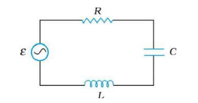
  1. Figure shows a series LCR circuit connected to a variable frequency 23...

    Text Solution

    |

  2. For current entering at A, the electric field E(r at a distance r form...

    Text Solution

    |

  3. A material 'B' has twice the specific resistance of 'A'. A circular wi...

    Text Solution

    |

  4. The length of a given cylindrical wire is increased by 100%. Due to th...

    Text Solution

    |

  5. If a wire is stretched to make it 0.1% longer, its resistance of will

    Text Solution

    |

  6. An electric current is passed through a circuit containing two wires o...

    Text Solution

    |

  7. By increasing the temperature, the specific resistance of a conductor ...

    Text Solution

    |

  8. A strip of copper another of germanium are cooled from room temperatur...

    Text Solution

    |

  9. The difference in the variation o resistance with temperature in a met...

    Text Solution

    |

  10. The thermistors are usually made of

    Text Solution

    |

  11. The resistance of a bulb filmanet is 100Omega at a temperature of 100^...

    Text Solution

    |

  12. The resistance of a wire is 5 ohm at 50^@C and 6 ohm at 100^@C. The re...

    Text Solution

    |

  13. The resistance of hot tungsten filament is about 10 times the cold res...

    Text Solution

    |

  14. An electric bulb is rated 220 V and 100 W. when it is operated on 110 ...

    Text Solution

    |

  15. An 220 volt-1000 watt bulb is connected across a 110 volt mains supply...

    Text Solution

    |

  16. A heater coil is cut into two equal parts and only one part is now use...

    Text Solution

    |

  17. If in the circuit, power dissipation is 150 W, then R is

    Text Solution

    |

  18. A wire when connected to 220 V mains supply has power dissipation P1. ...

    Text Solution

    |

  19. The resistance of the series combination of two resistances is S. WHen...

    Text Solution

    |

  20. A 3 V battery with negligible internal resistance is connected in a ci...

    Text Solution

    |

  21. What will be the value of current through 2Omega resistance for the ci...

    Text Solution

    |