 What is the potential difference between base and collector


Topper's Solved these Questions
Similar Questions
Explore conceptually related problems
MODERN PUBLICATION-SEMICONDUCTOR DEVICES-EXERCISE
- In a common base transistor amplifier, if the input resistance is 200 ...
Text Solution
|
- In a common base transistor amplifier, if the input resistance is 200 ...
Text Solution
|
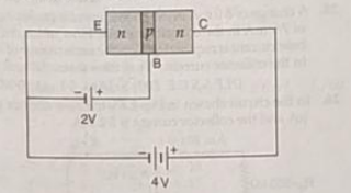
- In the n-p-n transistor circuit shown in the figure. What is the po...
Text Solution
|
- In the n-p-n transistor circuit shown in the figure. What is the bi...
Text Solution
|
- Calculate emitter current for which beta = 100 and base current Ib = 2...
Text Solution
|
- For a common emitter amplifier current gain = 50 if the emitter curren...
Text Solution
|
- In a common-emitter mode of transistor d.c. current gain is 20 and the...
Text Solution
|
- In a common-emitter mode of transistor d.c. current gain is 20 and the...
Text Solution
|
- The current gain of a transistor in a common base arrangement is 0.95....
Text Solution
|
- A common-emitter circuit has an input resistance of 0.6 kOmega and out...
Text Solution
|
- In a common emitter amplifier, using output reisistance of 5000 ohm an...
Text Solution
|
- A transistor connected in common emitter configuration has input resis...
Text Solution
|
- For a common emitter amplifier , current gain is 70 . If the emitter i...
Text Solution
|
- A common-emitter circuit has an input resistance of 0.6 kOmega and out...
Text Solution
|
- the input resistance of a comon-emitter amplifier is 2kOmega and a.c. ...
Text Solution
|
- the input resistance of a comon-emitter amplifier is 2kOmega and a.c. ...
Text Solution
|
- In a transistor, a change of 7.9 mA in emitter current produces a cha...
Text Solution
|
- Two amplifiers having voltage gains 20 and 50 are connected as shown i...
Text Solution
|
- A crystal diode having internal resistance 200Omega is used as a half ...
Text Solution
|
- A crystal diode having internal resistance 200Omega is used as a half ...
Text Solution
|