Home
Class 12
PHYSICS
Figure shown an imaginary cube of edge ...

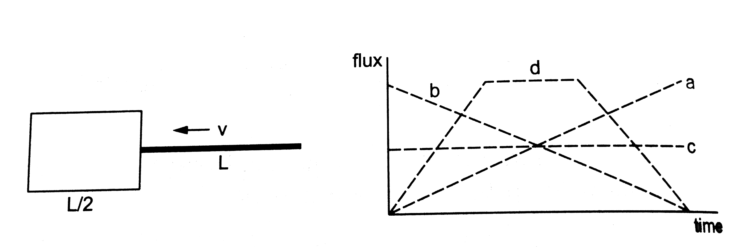
Figure shown an imaginary cube of edge L/2. A uniformly Charged rod of length L moves towards left at a small but constant speed v. At t=0, the left end just touches the centre of the cube opposite it. Which of the graphs shown in figure represents the flux of the electic field through the cube as the rod goes through it?

Text Solution

Verified by Experts

The correct Answer is:
D
Promotional Banner

Topper's Solved these Questions

Similar Questions

Explore conceptually related problems

A charge Q is placed at a distance a/2 above the centre of a horizontal, square surface of edge a as shown in figure. Find the flux of the electric field through the square surface.

A charge Q is uniformly distributed over a rod of length iota . Condider a hypothetical cube of edge iota with the centre of the cube at one end of the rod. Find the minimum possible flux of the electric field through the entire surface of the cube.

A point charge +10mu C is at a distance 5 cm directly above the centre of a square of side 10 cm, as shown in figure. What is the magnitude of the electric flux through the square? (Hint: Think of the square as one face of a cube with edge 10cm)

A rod of length L and mass M is hinged at point O. A small bullet of mass m ihits the rod with velocity v as shown in the figure. The bullet gets embedded in the rod. Calculate the angular velocity of the system just after the impact?

A rod of length L and mass M is hinged at point O. A small bullet of mass m ihits the rod with velocity v as shown in the figure. The bullet gets embedded in the rod. Calculate the angular velocity of the system just after the impact?

A uniform rod of mass m and length l is suspended through a light wire of length l and torsional constant k as shown in figure. Find the time period of the system makes small oscillations in the vertical plane about the suspension point .

Shown a circular coil of N turns and radius a, connected to a battery of emf epsilon through a rheostat. The rheostat has a total length L and resistance R. The resistance of the coil is r. A small circular loop of radius a' and resistance r' is placed coaxially with the coil. The centre of the loop is at a distance x from the centre of hte coil. In the beginning, the sliding contact of the rehostat is at the left end and then on wards it is moved towards right at a constant speed v. Find the emf induced int he small circular loop at the instant (a) the contact begins to slide and (b) it has slid thrugh half the length of the rheostat.

Figure shows a metal rod PQ resting on the smooth rails AB and positioned between the poles of a permanent magnet. The rails, the rod and the magnetic field are in three mutually perpendicular directions. A galvonometer G connects the rails through a switch K. Length of rod = 15 cm, B = 0.50 T, resistance of the closed loop containing the rod = 9.0mOmega . Assume the field to be uniform. a. Suppose K is open and the rod is moved with a speed of 12cms^(-1) in the direction shown. Give the polarity and magnitude of the induced emf. b. Is there an excess charge built up at the ends of the rods when K is open? What if K is closed? c. With K open and the rod moving uniformly, there is no net force on the electrons in the rod PQ eventhough they do experience magnetic force due to the motion of the rod. Explain. d. What is the retarding force on the rod when K is closed? e. How much power is required (by an external agent) to keep the rod moving at the same speed (=12cms^(-1)) when K is closed? How much power is required when K is open? f. How much power is dissipated as heat in the closed circuit? What is the source of this power? g. What is the induced emf in the moving rod if the magnetic field is parallel to the rails instead of being perpendicular?

Shows a rod PQ of length 20.0 cm and mass 200g suspended through a fixed point O by two threads of lengths 20.0 cm each. A magnetic field of strenght 0.500 T exists in the vicinity of the wire PQ as shown in the figure. The exists in the vicinity of the wire PQ as shown in the figure. The wires conecting PQ with the battery are loose and exert no force on PQ.(a) find the tension in the threads when the switch S is open. (b) A current of 2.0 A is established when the switch S is closed. Find the tension in the threads now.

Shown a metallic square frame of edga a in a vertical plane. A uniform magnetic field B exists in the space in a directon perpendicular to the plane of the figure. Two boys pull the opposite corners of the square ot deform it into a rhombus. They start pulling the corners t t=0 and sisplace the corners at a uniform speed u. (a) find the induced emf in the frame at the instant when the angles at these corners reduce to 60^@ . (b) find the induced current in the frame at this instatnt if the total resistance of the frame is R. (c) Find the total charge which flows through a side of the frame by the time the square is deformed into a straight line.