Home
Class 12
PHYSICS
What should be the value of R in figure ...

What should be the value of R in figure of which the current in it is zero?

Text Solution

Verified by Experts

Current value of R, the current in the
branch is Q.
Promotional Banner

Topper's Solved these Questions

  • ELECTRIC CURRENT IN CONDUCTORS

    HC VERMA|Exercise objective 2|9 Videos
  • DISPERSION AND SPECTRA

    HC VERMA|Exercise Exercises|11 Videos
  • ELECTRIC CURRENT THROUGH GASES

    HC VERMA|Exercise Exercise|23 Videos

Similar Questions

Explore conceptually related problems

What is the value of inductance L for which the current is a maximum in a series LCR circuit with C= 10 muF and w= 1000s^(-1)

Find the value of R in figure so that there is no current in the 50(Omega) resistor.

For a CE transistor amplifier , the audio signal voltage across the collector resistance of 2.0 k Omega is 2.0 V . Suppose the current amplification factor of the transistor is 100 . What should be the value of R_(R) in series with V_(BB) supply of 2.0V if the dc base current has to be 10 times the signal current . Also calculate then de drop across the collector resistance . Take VBE=0.6V

An inductor of inductance 100 mH is connected in series with a resistance, a variable capacitance and an AC source of frequency 2.0 kHz . What should be the value of the capacitance so that maximum current may be drawn into the circuit?

Find the value of current I in the circuit shown in figure.

An inductance of 2.0 H , a capacitance of 18 muF and a resistance of 10 kOmega are connected to an AC source of 20 V with adjustable frequency. (a) What frequency should be chosen to maximise the current in the circuit? (b) What is the value of this maximum current?

Consider the situation shown in the figure of the previous problem. Suppose the wire connecting O and C has zero resistance but circular loop has a resistance R uniformly distributed along its length. The rod OA is made to rotate with a uniform angular speed omega as shown in the figure. Find the current in the rod when ltAOC = 90^@ .

What is the value of zero kelvin on Celsius scale?

The given circuit has two ideal diodes connected as shown in the figure below. The current flowing through the resistance R_1 will be

HC VERMA-ELECTRIC CURRENT IN CONDUCTORS-Exercises
  1. Find the current through the 10(Omega)resistor shown in figure.

    Text Solution

    |

  2. Find the current in the resistor shown in figure.

    Text Solution

    |

  3. What should be the value of R in figure of which the current in it is ...

    Text Solution

    |

  4. Find the equivalent resistance of the circuit shown in figure between ...

    Text Solution

    |

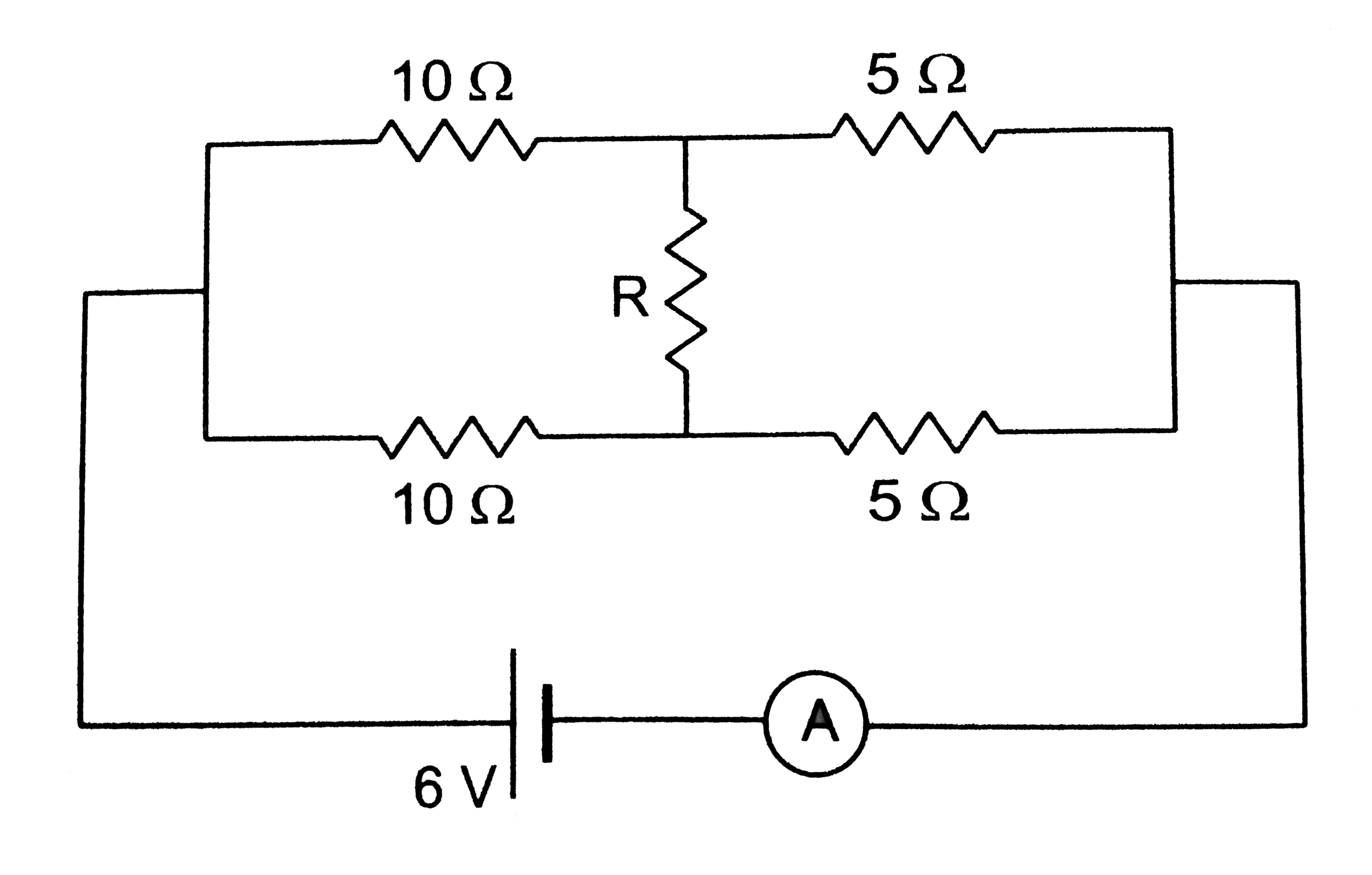
  5. Find the current measured by the ammeter in the circuit shown in figur...

    Text Solution

    |

  6. Consider the circuit shown in figure.Find (a) the current in the circu...

    Text Solution

    |

  7. Twelve wire, each having equal resistance r, are joined to form a cube...

    Text Solution

    |

  8. Find the equivalent resistances of the network shown in figure between...

    Text Solution

    |

  9. An infinite ladder is constructed with 1(Omega)and 2(Omega)resistor as...

    Text Solution

    |

  10. The emf (epsilon)and the internal resistance r of the battery shown in...

    Text Solution

    |

  11. A voltmeter of resistances 400(Omega)is used to measure the potential ...

    Text Solution

    |

  12. The voltmeter shown in figure reads 18V across the 50(Omega)resistor. ...

    Text Solution

    |

  13. A voltmeter consists of a 25(Omega) coil connected in series with a 57...

    Text Solution

    |

  14. An ammeter is to be constructed which can read currents up to 2.0A. If...

    Text Solution

    |

  15. A voltmeter coil has resistance 50.0(Omega)and a resistor of 1.15k(Ome...

    Text Solution

    |

  16. The potentiometer wire AB shown in figure is 40 cm long. Where should ...

    Text Solution

    |

  17. The potentiometer wire AB shown in figure is 50cm long.When AD=30cm, n...

    Text Solution

    |

  18. A 6-volt battery of negligible internal resistance is connected across...

    Text Solution

    |

  19. Consider the potentiometer circuit arranged as in figure. The potentio...

    Text Solution

    |

  20. Find the charge on the capacitor shown in figure

    Text Solution

    |