Home
Class 12
PHYSICS
The graph shows the variation of volatag...

The graph shows the variation of volatage 'v' across the plates of two capacitors A & B versus increase of charge 'Q' stored on them. Which of the two capacitors has higher capacitance? Give reason.

Text Solution

Verified by Experts

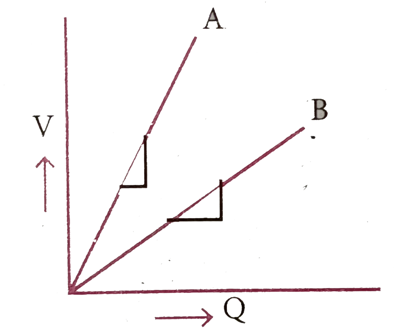
`C=(Q)/(V)=(1)/("slope")`
As slope of A is smaller capacitance of A is higher.
Promotional Banner

Similar Questions

Explore conceptually related problems

The graph shown here shows the variation of total energy (E) stored in a capacitor (c) itself. Which of the two is kept constant for this graph, whatever the charge an capacitor of the potential used to charge it?

For the given capacitor configuration (a) Find the charges on each capacitor (b) potential difference across them ( c) energy stored in each capacitor .

A capacitor of capacitor of capacitance 2.0muF is charge to a potential diffrence of 12V It is then connected of uncharged capacitor of capacitance 4.0muF as shown in figure . Find (a ) the charge on each of the two capacitors after the connection, (b ) the electrostatic energy stored in each of the two capacitors.

A capacitor of capacitance 12.0 muF is joined to an AC source of frequency 200 Hz . The rms current in the circuit is 2.00 A . (a) Find the rms voltage across the capacitor. (b) Find the average energy stored in the electric field between the plates of the capacitor.

A capacitor having a capacitance of 100muF is charged to a potential difference of 24V . The charging battery is disconnected and the capacitor is connected to another battery of emf 12V with the positive plate of the capacitor joined with the positive terminal of the battery . (a ) Find the charges on the capacitor before and after the reconnection . (b ) Find the charge flown through the 12V battery . (c ) Is work done by the battery or is it done on the battery ? find its magnitude . (d ) Find the decrease in electrostatic field energy . (e ) Find the best developed during the flow of charge after reconnection.

A thin metal plate P is inserted between the plates of a parallel-plate capacitor of capacitance C in such a way that its edges touch the two plates (figure 31-Q2).The capacitance now becomes.