A
B
C
D
Text Solution
AI Generated Solution
The correct Answer is:


Recommended Questions
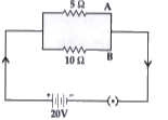
- Two conductors A and B resistance 5 omega and 10 omega respectively ar...
Text Solution
|
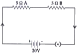
- The resistance of two conductors in series is 40 Omega and their resis...
Text Solution
|
- The resistance of two conductors in series is 18 Omega and the resista...
Text Solution
|
- यदि दो चालकों को श्रेणीक्रम एवं समांतरक्रम में जोड़ने पर उनके समतुल्...
Text Solution
|
- Two cells, of voltage 10 V and 2 V and internal resistances 10 Omega a...
Text Solution
|
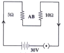
- Two conductors A and B of resistances 5 Omega and 10 Omega respectivel...
Text Solution
|
- Two conductors A and B of resistances 5 Omega and 10 Omega respectivel...
Text Solution
|
- Two resistors X and Y of resistances 2 omega and 3 omega respectively ...
Text Solution
|
- 10 resistors of 5 Omega value are first connected in series then in p...
Text Solution
|