A
B
C
D
Text Solution
Verified by Experts
The correct Answer is:


Topper's Solved these Questions
Similar Questions
Explore conceptually related problems
NTA MOCK TESTS-NTA TPC JEE MAIN TEST 100-PHYSICS (SUBJECTIVE NUMERICAL)
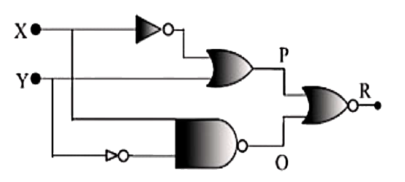
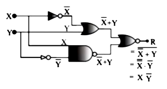
- The figure gives a system of logic gates. From the study of the truth ...
Text Solution
|
- If in nuclear fission, a piece of uranium of mass 0.5g is lost, the en...
Text Solution
|
- The power dissipated (in watt) in 3Omega resistance in the following c...
Text Solution
|
- Charges Q, 2Q, and -Q are given to three concentric conducting spheric...
Text Solution
|
- A man throws a ball of mass m from a moving plank (A). The ball has a ...
Text Solution
|
- Initially, both the blocks are at rest on horizontal surface as shown ...
Text Solution
|
- A sound source S, emitting a sound of frequency 400 Hz and a receiver ...
Text Solution
|
- A wire suspended vertically from one of the its ends is stretched by a...
Text Solution
|
- At what distance (in m) from a convex mirror of focal length 2.5 m sh...
Text Solution
|
- A beam of light consisting of two wavelengths, 650 nm and 520 nm is us...
Text Solution
|
- The potential energy of a particle of mass 5 kg moving in the x-y plan...
Text Solution
|