A
B
C
D
Text Solution
Verified by Experts
The correct Answer is:


Topper's Solved these Questions
CAPACITORS
AAKASH SERIES|Exercise PRACTICE SHEET (ADVANCED) (Linked Comprehension Type Questions Passage)|1 VideosCAPACITORS
AAKASH SERIES|Exercise PRACTICE SHEET (ADVANCED) (Integer Type Questions)|2 VideosCAPACITORS
AAKASH SERIES|Exercise ADDITIONAL PRACTICE EXERCISE (LEVEL - II LECTURE SHEET (ADVANCED))(Integer Type Questions )|3 VideosATOMS
AAKASH SERIES|Exercise PRACTICE EXERCISE|21 VideosCOMMUNICATION SYSTEM
AAKASH SERIES|Exercise LECTURE SHEET (LEVEL - I) (MAIN) (EXERCISE - IV) (Straight Objective & More than one Correct Answer Type Questions)|20 Videos
Similar Questions
Explore conceptually related problems
AAKASH SERIES-CAPACITORS -PRACTICE SHEET (ADVANCED) (Straight Objective Type Questions)
- A parallel plate capacitor C with plates of unit area and separaion d ...
Text Solution
|
- A variable air capacitor used in radio tuning circuit is made of N sem...
Text Solution
|
- A sperical capacitor composed of two concentric metal spheres one havi...
Text Solution
|
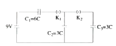
- In the ciruit shown in figure, Initially K1 is closed and K2 is open...
Text Solution
|
- In capacitor bridge, a voltage V0 is applied and the variable capacit...
Text Solution
|
- Twelve capacitors, each having a capacitance C, are connected to form ...
Text Solution
|
- A combination of capacitors given is charged by a cell of emf E as sho...
Text Solution
|
- A combination of capacitors given is charged by a cell of emf E as sho...
Text Solution
|
- Match the refining methods (Column I) with (Column II).
Text Solution
|