A
B
C
D
Text Solution
Verified by Experts
The correct Answer is:


Topper's Solved these Questions
CURRENT ELECTRICITY
AAKASH SERIES|Exercise LECTURE SHEET (EXERCISE-VII LEVEL-II (ADVANCED) (Straight Objective Type Questions))|5 VideosCURRENT ELECTRICITY
AAKASH SERIES|Exercise LECTURE SHEET (EXERCISE-VII LEVEL-II (ADVANCED) (Linked Comprehension Type Questions))|3 VideosCURRENT ELECTRICITY
AAKASH SERIES|Exercise LECTURE SHEET (EXERCISE-VI LEVEL- II (ADVANCED) (Straight Objective Type Questions))|7 VideosCURRENT ELECTRICITY
AAKASH SERIES|Exercise PROBLEMS (LEVEL-II)|27 VideosDUAL NATURE OF RADIATION AND MATTER
AAKASH SERIES|Exercise PRACTICE EXERCISEX|42 Videos
Similar Questions
Explore conceptually related problems
AAKASH SERIES-CURRENT ELECTRICITY-LECTURE SHEET (EXERCISE-VII LEVEL - I (MAIN) (Straight Objective Type Questions))
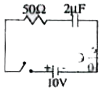
- For the circuit shown in the figure, determine the charge of capacitor...
Text Solution
|
- A capacitor is charged steadily from a DC source. Correct variation of...
Text Solution
|
- In the steady state, the charge on the capacitor capacity 0.2 muF is
Text Solution
|
- Three identical capacitors are charged by connecting them in parallel ...
Text Solution
|
- For the circuit shown in figure below, at t = 0, switch is closed, the...
Text Solution
|
- For the given circuit shown in figure below, time constant is
Text Solution
|
- During charging of capacitor in the circuit shown, Circuit curren...
Text Solution
|
- During discharging of a capacitor via a resistor Circuit current ...
Text Solution
|
- If the capacitor shown in the circuit is charged to 5V and left in the...
Text Solution
|