A
B
C
D
Text Solution
Verified by Experts
The correct Answer is:


Topper's Solved these Questions
CURRENT ELECTRICITY
AAKASH SERIES|Exercise PRACTICE SHEET (EXERCISE - VII LEVEL-II (ADVANCED) (Straight Objective Type Questions))|4 VideosCURRENT ELECTRICITY
AAKASH SERIES|Exercise PRACTICE SHEET (EXERCISE - VII LEVEL-II (ADVANCED) (More than One correct answer Type Questions))|2 VideosCURRENT ELECTRICITY
AAKASH SERIES|Exercise PRACTICE SHEET (EXERCISE - VI LEVEL-II (ADVANCED) (Linked Comprehension Type Questions))|3 VideosCURRENT ELECTRICITY
AAKASH SERIES|Exercise PROBLEMS (LEVEL-II)|27 VideosDUAL NATURE OF RADIATION AND MATTER
AAKASH SERIES|Exercise PRACTICE EXERCISEX|42 Videos
Similar Questions
Explore conceptually related problems
AAKASH SERIES-CURRENT ELECTRICITY-PRACTICE SHEET (EXERCISE - VII LEVEL-I (MAIN) (Straight Objective Type Questions))
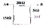
- The value of the resistance as measured across terminals A and B in fi...
Text Solution
|
- How many time constants will elapse before the current in a charging R...
Text Solution
|
- How many time constants will elapse before the energy stored in the ca...
Text Solution
|
- how many time constants will elapse before the power delovered by the ...
Text Solution
|
- In the transient circuit shown, the time constant of the circuit is :
Text Solution
|