Text Solution
Verified by Experts
The correct Answer is:


Topper's Solved these Questions
CURRENT ELECTRICITY
AAKASH SERIES|Exercise ADDITIONAL PRACTICE EXERCISE (LEVEL -II PRACTICE SHEET (ADVANCED) (Straight Objective Type Questions))|5 VideosCURRENT ELECTRICITY
AAKASH SERIES|Exercise ADDITIONAL PRACTICE EXERCISE (LEVEL -II PRACTICE SHEET (ADVANCED) (More than One correct answer Type Questions))|5 VideosCURRENT ELECTRICITY
AAKASH SERIES|Exercise ADDITIONAL PRACTICE EXERCISE (LEVEL -II LECTURE SHEET (ADVANCED) (Matrix Matching Type Questions))|2 VideosCURRENT ELECTRICITY
AAKASH SERIES|Exercise PROBLEMS (LEVEL-II)|27 VideosDUAL NATURE OF RADIATION AND MATTER
AAKASH SERIES|Exercise PRACTICE EXERCISEX|42 Videos
Similar Questions
Explore conceptually related problems
AAKASH SERIES-CURRENT ELECTRICITY-ADDITIONAL PRACTICE EXERCISE (LEVEL -II LECTURE SHEET (ADVANCED) (Integer Type Questions))
- Current density in a cylindrical wire of radius R is given as J={(J(0...
Text Solution
|
- A copper of rod (resistivity 2.2 xx 10^(-8) Omega -m) and an iron (r...
Text Solution
|
- Consider a copper cylinder of volume x, resistivity f, resistance acro...
Text Solution
|
- One kilowatt electric heater is to be used with 220V DC supply. It con...
Text Solution
|
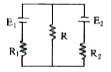
- In the circuit shown in figure R(1)=R(2)=10Omega, E(1)=20V, E(2)=40V. ...
Text Solution
|
- A capacitor C = 100 muF is connected to three resistance each of resis...
Text Solution
|
- A galvanometer having a resistance of 50Omega, gives a full scale defl...
Text Solution
|
- In the arrangement shows in fig. , when the switch S2 is open, the gal...
Text Solution
|