Home
Class 12
PHYSICS
Input characteristics are shown for CE c...

Input characteristics are shown for CE configuration of n-p-n transistor for different output voltage. Here.

A

A) `V_("CE"_(1) ) gt V_("CE"_(2) )`

B

B) `V_("CE"_(1) )`

C

C) `V_("CE"_(1) ) lt V_("CE"_(2) )`

D

D) none of these

Text Solution

Verified by Experts

The correct Answer is:
A
Promotional Banner

Topper's Solved these Questions

  • PRACTICAL PHYSICS

    AAKASH SERIES|Exercise LECTURE SHEET LEVEL-II (ADVANCED) Linked Comprehension Type Questions|4 Videos
  • PRACTICAL PHYSICS

    AAKASH SERIES|Exercise LECTURE SHEET LEVEL-II (ADVANCED) Linked Comprehension Type Questions|4 Videos
  • PHYSICAL WORLD

    AAKASH SERIES|Exercise Exercise -I|10 Videos
  • RAY OPTICS

    AAKASH SERIES|Exercise PROBLEMS ( LEVEL-II)|60 Videos

Similar Questions

Explore conceptually related problems

A n-p-n transistor conducts when

The symbol of p-n-p transistor is

The number of terminals in n-p-n transistor is

(a) Describe briefly the functions of the three segments of n-p-n transistor. (b) Draw the circuit arrangment for studying the output characterstics of n-p-n transistor in CE configuration. Explain how the output characterstics is obtained.

Output characteristics of an n-p-n transistor in CE configuration is shown in the Fig. Determine (i) dynamic output resistance (ii) dc current gain and (iii) ac current gain at an opererating point V_(CE)=10V , when I_(B)=30muA .

In the following common emitter configuration an n-p-n transistor with current gain beta=100 is used. What is the output voltage of the amplifier ?

Draw typical output characteristics of an n-p-n transistor in CE configuration. Show how these characteristics can be used to determine output resistance.

Draw the diagram of the circuit arangement used for studying the 'input' and the 'output' characteristics of an n-p-n transistor inits CE configuration. Briefly explain how these two types of characteristics are obtained and draw these characteristics. (b) 'Define' the terms (i) Input resistance, (ii) Output resistance , (iii) Current amplification factor, for a given transistor.

(i) Draw a circuit diagram to study the input and output characteristics of an n-p-n transistor in its common emitter configuration. Draw the typical input and output characteristics. (ii) Explain, with the hepl of a circuit diagram, the working of n-p-n transistor as a common emitter amplifier.

Consider the circuit arrangnent shown in Fig. for studying input and output characteristics of npn transistor in CE configuration. Select the values of R_ and R_ for a transistor whose V_(BE)=0.7V , so that the transistor is operating at point Q as shown in the characteristics shown in Fig. Given that the input impedance of the transistor is very small and V_(C C)=V_(BB)=16V , also find the voltage gain and power gain of circuit making appropriate assumptions.

AAKASH SERIES-PRACTICAL PHYSICS-LECTURE SHEET LEVEL-II (ADVANCED) Straight Objective Type Questions
  1. If m and M are the masses of two bodies that are tied at two ends of a...

    Text Solution

    |

  2. In remeasurement of mass of a given object by the principle of moments...

    Text Solution

    |

  3. In experiment for measuring surface tension by capillary rise method, ...

    Text Solution

    |

  4. In the experiment of finding speed of sound by resonance tube, it is o...

    Text Solution

    |

  5. If velocity of sound at room temperature is 35078 cm s^(-1), then velo...

    Text Solution

    |

  6. A heating curve has been plotted for a solid object as shown in the fi...

    Text Solution

    |

  7. Which one is correct ?

    Text Solution

    |

  8. To identify whether the transistor is working or not, using multimeter...

    Text Solution

    |

  9. Consider the transistor shown in figure, its terminals are marked as 1...

    Text Solution

    |

  10. In the previous question the tension in the string is

    Text Solution

    |

  11. The circuit diagram below shows n-p-n transistor in CE configuration. ...

    Text Solution

    |

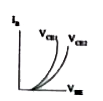
  12. Input characteristics are shown for CE configuration of n-p-n transist...

    Text Solution

    |

  13. A zener diode is operating in its normal region i.e., the breakdown re...

    Text Solution

    |

  14. The forward bias characteristics of two diodes D(1) and D(2) are shown...

    Text Solution

    |

  15. In U - V method, the object distance is 30.0cm and image distance is 6...

    Text Solution

    |

  16. Displacement method is applicable to determine the focal length of con...

    Text Solution

    |

  17. A meter bridge is set- up as shown in figure, to determine an unknown ...

    Text Solution

    |

  18. In the experiment to determine the speed of sound using a resonance co...

    Text Solution

    |

  19. A vernier callipers is constructed by using two identical triangular w...

    Text Solution

    |