A
B
C
D
Text Solution
Verified by Experts
The correct Answer is:


Topper's Solved these Questions
ELECTROMAGNETIC INDUCTION
AAKASH SERIES|Exercise EXERCISE - I (SELF AND MUTUAL INDUCTION)|16 VideosELECTROMAGNETIC INDUCTION
AAKASH SERIES|Exercise EXERCISE - I (ASSERTION AND REASON)|14 VideosELECTROMAGNETIC INDUCTION
AAKASH SERIES|Exercise EXERCISE-III|29 VideosELECTRIC FIELD AND POTENTIAL
AAKASH SERIES|Exercise PROBLEMS (LEVEL-II)|26 VideosELECTROMAGNETIC WAVES
AAKASH SERIES|Exercise EXERCISE -II|22 Videos
Similar Questions
Explore conceptually related problems
AAKASH SERIES-ELECTROMAGNETIC INDUCTION-EXERCISE - I (MAGNETIC FLUX, FARADAY.S LAW, LENZ.S LAW, AC GENERATOR)
- As shown in the figure, à magnet is moved with a fast speed towards a ...
Text Solution
|
- Two different loops are concentric and lie in the same plane. The curr...
Text Solution
|
- A magnet is dropped dwon an infinitely long vertical copper tube,
Text Solution
|
- A magnet N-S is suspended from a spring and while at oscillates, the m...
Text Solution
|
- An infinitely long cylinder is kept parallel to a uniform magnetic fie...
Text Solution
|
- Two coils of wires A and B are mutually at right angles to each other ...
Text Solution
|
- In the given figure, the north pole of a magnet is brought towards a c...
Text Solution
|
- Two identical circular loops of metal wires are lying on a table witho...
Text Solution
|
- A circular loop of radius R, carrying current I, lies in x-y plane wit...
Text Solution
|
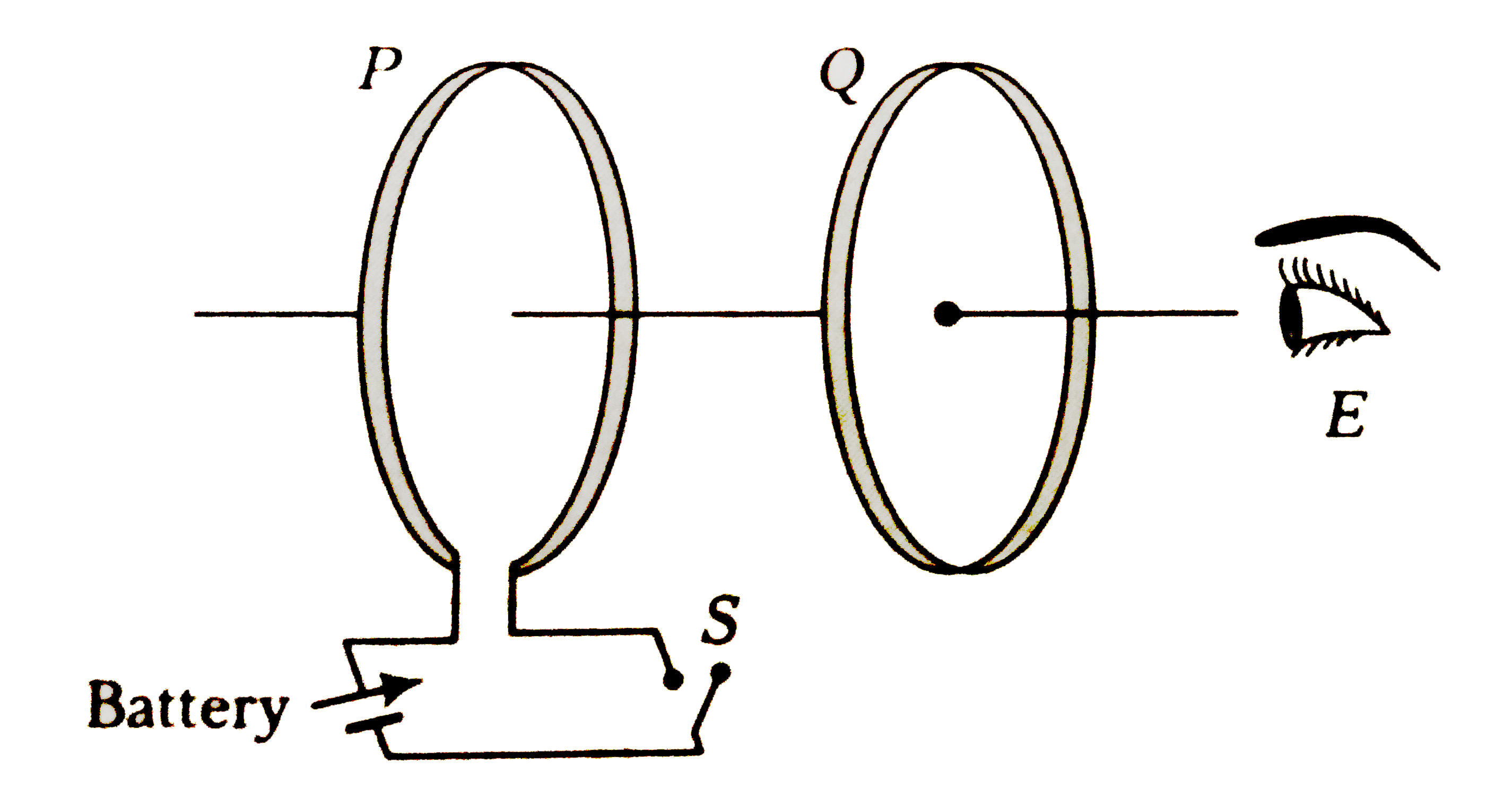
- As shown in figure, P and Q are two co-axial conducting loops separate...
Text Solution
|
- The variation of induced emf (epsilon ) with time (t) in a coil if a s...
Text Solution
|
- A current carrying wire is placed below a coil in its plane, with curr...
Text Solution
|
- A conducting bar is pulled with a constant speed v on a smooth conduct...
Text Solution
|
- A coil is rotated in a uniform magnetic field about an axis perpendicu...
Text Solution
|
- A magnet with its north pole pointing down wards along the axis of an ...
Text Solution
|
- The north of a bar magnet is moved towards a coil along the axis passi...
Text Solution
|
- A metalic square loop ABCD is moving in its own plane with velocity v ...
Text Solution
|
- A conducting wire frame is placed is placed in a magnetic field which ...
Text Solution
|
- A metallic ring is connected to a rod oscillates freely like a pendulu...
Text Solution
|
- In an experiment, a magnet with its magnetic moment along the axis of ...
Text Solution
|