A
B
C
D
Text Solution
Verified by Experts
The correct Answer is:


Topper's Solved these Questions
Similar Questions
Explore conceptually related problems
AAKASH SERIES-SEMICONDUCTOR DEVICES-EXERCISE - II
- The input signal given to a CE amplifier having a voltage gain of 150 ...
Text Solution
|
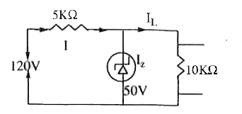
- In the figure shown, the currents through the series resistance and lo...
Text Solution
|
- The current gain of a transistor in common base and common-emitter con...
Text Solution
|
- For a transistor,alpha = 0.9, the value of beta is
Text Solution
|
- Calculate the current amplification factor beta when change in collect...
Text Solution
|
- The emitter current in a transistor is 2.2mA and the collector current...
Text Solution
|
- While a collector-emitter voltage is constant in a transistor, the col...
Text Solution
|
- Which of the following logic gates the given truth table represents
Text Solution
|
- The logic symbol shown in figure represents
Text Solution
|
- The arrangement shown in figure performs the logic function of
Text Solution
|
- Given below are four logic gate symbols. Those for OR, NOR and AND are...
Text Solution
|
- Identify the gate represented by the block diagram is
Text Solution
|
- In Boolean expression which gate is expressed as y = bar(A +B)
Text Solution
|
- In the given Boolean expression, Y=A.bar(B)+B.barA, if A=1, B=1 then Y...
Text Solution
|
- The logic circuit shown below has the input waveforems 'A' and 'B' as ...
Text Solution
|
- In the circuit below, A and B represents two inputs and C represents t...
Text Solution
|
- Which one of the following represents forward basis diode ?
Text Solution
|