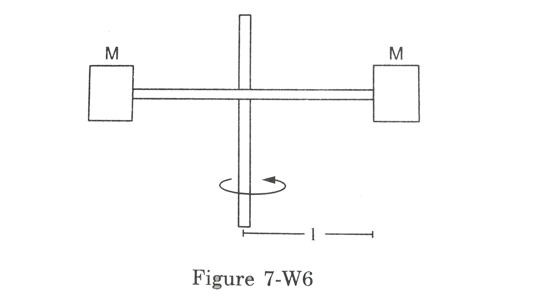
Two blocks each of mass M are connected to the ends of a light frame as shown in figure. The frame si rotated about the vertical line of symmetry. The rod breaks if the tension in it exceeds `T_0`. Find the maximum frequency with which the frame may be rotted without breaking the rod.
Two blocks each of mass M are connected to the ends of a light frame as shown in figure. The frame si rotated about the vertical line of symmetry. The rod breaks if the tension in it exceeds `T_0`. Find the maximum frequency with which the frame may be rotted without breaking the rod.
Text Solution
Verified by Experts
Consider one of the blocks. If the frequencey of revolution is f, the angular velocity is `omega=2pif`. The acceleration towards the centre is `v^2/l=omega^2l=4pi^2f^2l`. The only horizontal force on the blck is the tension of the rod. At the point of breaking this foce is `T_0`. So from Newton's second law
`T_0=M.4pi^2f^2l`
or `f=1/(2pi) [T_0/(Ml)]^(1/2)`
`T_0=M.4pi^2f^2l`
or `f=1/(2pi) [T_0/(Ml)]^(1/2)`


Similar Questions
Explore conceptually related problems
Block A of mass m//2 is connected to one end of light rope which passes over a pulley as shown in fig. A man of mass m climbs the other end of rope with a relative acceleration of g//6 with respect to rope. Find the acceleration of block A and tension in the rope.
A uniform thin cylindrical disk of mass M and radius R is attaached to two identical massless springs of spring constatn k which are fixed to the wall as shown in the figure. The springs are attached to the axle of the disk symmetrically on either side at a distance d from its centre. The axle is massless and both the springs and the axle are in horizontal plane. the unstretched length of each spring is L. The disk is initially at its equilibrium position with its centre of mass (CM) at a distance L from the wall. The disk rolls without slipping with velocity vecV_0 = vacV_0hati. The coefficinet of friction is mu. The maximum value of V_0 for whic the disk will roll without slipping is-
A uniform thin cylindrical disk of mass M and radius R is attaached to two identical massless springs of spring constatn k which are fixed to the wall as shown in the figure. The springs are attached to the axle of the disk symmetrically on either side at a distance d from its centre. The axle is massless and both the springs and the axle are in horizontal plane. the unstretched length of each spring is L. The disk is initially at its equilibrium position with its centre of mass (CM) at a distance L from the wall. The disk rolls without slipping with velocity vecV_0 = vacV_0hati. The coefficinet of friction is mu. The centre of mass of the disk undergoes simple harmonic motion with angular frequency omega equal to -
Two identical small balls each of mass m are rigidly affixed at the ends of light rigid rod of length 1.5 m and the assmebly is placed symmetrically on an elevated protrusion of width l as shown in the figure. The rod-ball assmebly is titled by a small angle theta in the vertical plane as shown in the figure and released. Estimate time-period (in seconds) of the oscillation of the rod-ball assembly assuming collisions of the rod with corners of the protrusion to be perfectly elastic and the rod does not slide on the corners. Assume theta=gl (numerically in radians), where g is the acceleration of free fall.
Two blocks each of mass m, connected by an un-stretched spring are kept at rest on a frictionless horizontal surface. A constant force F is applied on one of the blocks pulling it away from the other as shown in figure. (a)Find accelaration of the mass center. (b) Find the displacement of the centre of mass as function of time t. (c) If the extension of the spring is X_(0) at an instant t, find the displacements of the two blocks relative to the ground at this instant.
Two identical small discs each of mass m placed on a frictionless horizontal floor are connected with the help of a light spring of force constant k. The discs are also connected with two light rods each of length 2sqrt(2)m that are pivoted to a nail driven into the floor as shown as shown in the figure by a top view of the situation. If period of small oscillations of the system is 2pi sqrt((m//k)) , find relaxed length (in meters) of the spring.
Internal micrometer is a measuring intrument used to measure internal diameter (ID) of a large cylinder bore with high accuracy. Construction is shown in figure. There is one fixed rod B (to the right in figure) and one moved rod A (to the left in figure). It is based on the particle of advancement of a screw when it is rotated in a nut with internal threads. Main scale reading can be directly seen on the hub which is fixed with respect to rod B. When the cap is rotated rod A moves in or cut depending on direction of rotation. The circular scale reading is seen by checking which division of circular scale coincide with the references line This is to be multiplied by LC to get circular scale reading. Least count = value of 1 circular scale division = ("pitch")/("number of division on circular scale") Length of rod A is chosen to match the ID(PQ) to be measured. Zero error is checked by taking reading between standard blocks fixed at normal value of ID to be measured. Zero error is positive if cap end is one the right of the main scale and negative it is on the left side. In an internal micrometer, main scale division is of 0.5 mm and there are 50 divisions in circular scale. The least count of the instrument is-
Two blocks of mass m_(1)=10kg and m_(2)=5kg connected to each other by a massless inextensible string of length 0.3m are placed along a diameter of the turntable. The coefficient of friction between the table and m_(1) is 0.5 while there is no friction between m_(2) and the table. the table is rotating with an angular velocity of 10rad//s . about a vertical axis passing through its center O . the masses are placed along the diameter of the table on either side of the center O such that the mass m_(1) is at a distance of 0.124m from O . the masses are observed to be at a rest with respect to an observed on the tuntable (g=9.8m//s^(2)) . (a) Calculate the friction on m_(1) (b) What should be the minimum angular speed of the turntable so that the masses will slip from this position? (c ) How should the masses be placed with the string remaining taut so that there is no friction on m_(1) .
A frame of reference that is accelerated with respect to an inertial frame of reference is called a non-inertial frame of reference. A coordinate system fixed on a circular disc rotating about a fixed axis with a constant angular velocity omega is an example of non=inertial frame of reference. The relationship between the force vecF_(rot) experienced by a particle of mass m moving on the rotating disc and the force vecF_(in) experienced by the particle in an inertial frame of reference is vecF_(rot)=vecF_(i n)+2m(vecv_(rot)xxvec omega)+m(vec omegaxx vec r)xxvec omega . where vecv_(rot) is the velocity of the particle in the rotating frame of reference and vecr is the position vector of the particle with respect to the centre of the disc. Now consider a smooth slot along a diameter fo a disc of radius R rotating counter-clockwise with a constant angular speed omega about its vertical axis through its center. We assign a coordinate system with the origin at the center of the disc, the x-axis along the slot, the y-axis perpendicular to the slot and the z-axis along the rotation axis (vecomega=omegahatk) . A small block of mass m is gently placed in the slot at vecr(R//2)hati at t=0 and is constrained to move only along the slot. The distance r of the block at time is
A frame of reference that is accelerated with respect to an inertial frame of reference is called a non-inertial frame of reference. A coordinate system fixed on a circular disc rotating about a fixed axis with a constant angular velocity omega is an example of non=inertial frame of reference. The relationship between the force vecF_(rot) experienced by a particle of mass m moving on the rotating disc and the force vecF_(in) experienced by the particle in an inertial frame of reference is vecF_(rot)=vecF_(i n)+2m(vecv_(rot)xxvec omega)+m(vec omegaxx vec r)xxvec omega . where vecv_(rot) is the velocity of the particle in the rotating frame of reference and vecr is the position vector of the particle with respect to the centre of the disc. Now consider a smooth slot along a diameter fo a disc of radius R rotating counter-clockwise with a constant angular speed omega about its vertical axis through its center. We assign a coordinate system with the origin at the center of the disc, the x-axis along the slot, the y-axis perpendicular to the slot and the z-axis along the rotation axis (vecomega=omegahatk) . A small block of mass m is gently placed in the slot at vecr(R//2)hati at t=0 and is constrained to move only along the slot. The distance r of the block at time is
Recommended Questions
- Two blocks each of mass M are connected to the ends of a light frame a...
Text Solution
|
- Two blocks each of mass M are connected to the ends of a light frame a...
Text Solution
|
- A block of mass m is connected to a spring of spring constant k as sho...
Text Solution
|
- The rod AB oriented parallel to the x^' axis of the reference frame K^...
Text Solution
|
- Three massless rods are fixed to form a right angled triangular frame ...
Text Solution
|
- M द्रव्यमान के दो ब्लॉक एक नगण्य भार वाले फ्रेम में लगी एक नगण्य भार व...
Text Solution
|
- An equilateral triangular frame is made of three thin massless rods. T...
Text Solution
|
- As shown in the figure, a rod moves with v = 2 m/sec & rotates with om...
Text Solution
|
- Three indentical thin rods each of mass m and length L are joined toge...
Text Solution
|