Text Solution
Verified by Experts


Topper's Solved these Questions
Similar Questions
Explore conceptually related problems
HC VERMA-ELECTROMAGNETIC INDUCTION-EXERCISE
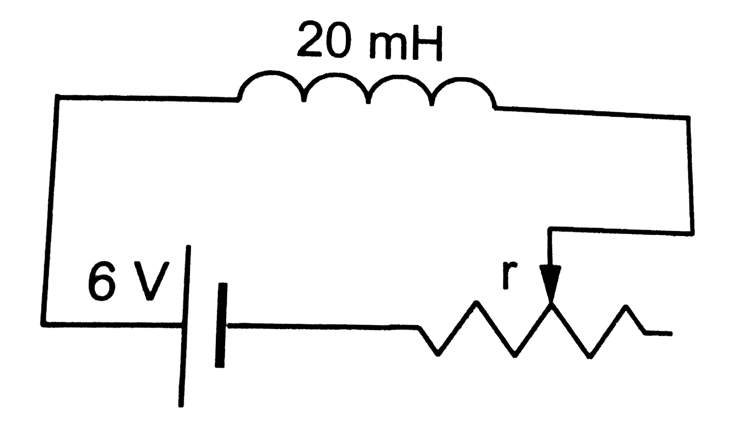
- Consider the circuit shown in the sliding contact is being pulled towa...
Text Solution
|
- Shown a metallic square frame of edga a in a vertical plane. A uniform...
Text Solution
|
- A wire loop confined in a plane is rotated in its oen plane with some ...
Text Solution
|
- Shown a circular coil of N turns and radius a, connected to a battery...
Text Solution
|
- A circular coil of one turn of radiius 5.0 cm is rotated about a diam...
Text Solution
|
- suppose the ends of the coil in the previous problem are connected to...
Text Solution
|
- An LR circuit constains an inductor of 500 mH, a resistor of 25.O Om...
Text Solution
|
- An LR circuit having a time constant of 50 ms is connected with an ide...
Text Solution
|
- Find the mutual inductance between the straight wire and the square lo...
Text Solution
|
- Find the mutual inductance between the circular coil and the loop show...
Text Solution
|