Home
Class 12
PHYSICS
Shows a wire ab of length l and resistan...

Shows a wire ab of length l and resistance R which can slide on a smooth pair of rails. `I_g` is a current generator which supplies a constand current in in the circuit. If the wire ab slides at a speed v towards right, find the potential difference betwwen `a and b`.

Text Solution

Verified by Experts

The moving wire ab is equivalent to a battery of emf vBl having a resistance R
if it moves towards right and the magnetic field is going into the plane of the figure, the force` vec qv X vecB` will push the positive charges towards a
Thus the positive terminal of the equivalent battery is towards a
An equivalent circuit is shown in fiegur
the potential difference between a and b is ` V_a - V_b = vBl - iR`
Promotional Banner

Topper's Solved these Questions

  • ELECTROMAGNETIC INDUCTION

    HC VERMA|Exercise Short Answer|13 Videos
  • ELECTROMAGNETIC INDUCTION

    HC VERMA|Exercise Objective 1|12 Videos
  • ELECTROMAGNETIC INDUCTION

    HC VERMA|Exercise EXERCISE|9 Videos
  • ELECTRIC FIELD AND POTENTIAL

    HC VERMA|Exercise Exercises|75 Videos
  • ELECTROMAGNETIC WAVES

    HC VERMA|Exercise Exercises|9 Videos

Similar Questions

Explore conceptually related problems

A magnetic field vecB=B_0 sin (omegat)hatk covers a large region where a wire AB slides smoothly over two parallel conductors separated by a distance d as in figure. The wires are in the xy-plane. The wire AB (of length d) has resistance R and the parallel wires have negligible resistance. If AB is moving with velocity v, what is the current in the circuit. What is the force needed to keep the wire moving at constant velocity ?

A uniform conducting wire of length 12a and resistance R is wound up as a current carrying coil in the shape of : (i) an equilateral triangle of side a, (ii) a square of sides a and, (iii) a regular hexagon of sides a. The coil is connected to a voltage source V_(0) . Find the magnetic moment of the coils in each case.

A ring is made of a wire having a resistance R_(0) = 12 Omega . Find the point A and B , as shown in the figure, at which a current carrying conductor should be connected so that the resistance R of the subcircuit between these points is equal to (8)/(3) Omega

There are 21 marks (zero to 20) on the dial of a galvanometer, that is there are 20 divisions. On passing 10muA current through it, it shows a deflection of 1 division. Its resistance is 20Omega . (a) How can it be converted into an ammeter which can measure 1 A current ? (b) How can we change it into a voltmeter to measure a pd of 1 V ? Also find the effective resistance of both of the above mentioned meters.

Find the current in the sliding rod AB (resistance = R) for the arrangement shown in figure. vecB is constant and is out of the paper. Parallel wires have no resistance, v is constant. Switch S is closed at time t = 0.

Find the current in the sliding rod AB (resistance = R) for the arrangement shown in figure. vecB is constant and is out of the paper. Parallel wires have no resistance, v is constant. Switch S is closed at time t = 0.

A conducting wire XY of mass m and neglibile resistance slides smoothly on two parallel conducting wires as shown in figure. The closed circuit has a resistance R due to AC. AB and CD are perfect conductors. There is a magnetic field vecB=B(t)hatk (i) Write down equation for the acceleration of the wire XY. (ii) If vecB is independent of time, obtain v(t), assuming v (0) = u_0 . (iii) For (ii), show that the decrease in kinetic energy of XY equals the heat lost in.

A rectangular conducting loop consists of two wires on two opposite sides of length 1 joined together by rods of length d. The wires are each of the same material but with cross sections differing by a factor of 2. The thicker wire has a resistance R and the rods are of low resistance, which in turn are connected to a constant voltage source V_(0) . The loop is placed in uniform a magnetic field vecB at 45^(@) to its plane. Find the torque exerted by the magnetic field on the loop about an axis through the centres of rods.

A sinusoidal voltage of peak value 283 V and frequency 50 Hz is applied to a series LCR circuit in which R=6 Omega , L=50.96 mH and C=398 muF . Find the phase difference between the voltage across the source and the current .

HC VERMA-ELECTROMAGNETIC INDUCTION-Worked Out Examples
  1. Shows a horizontal magnetic field which is uniform above the dotted li...

    Text Solution

    |

  2. Shows a wire of length l which can slide on a U- shaped rail of neglig...

    Text Solution

    |

  3. A rod of length l is translating at a velocity v making an angle theta...

    Text Solution

    |

  4. The horizontal component of the earth's magnetic field at a place is 3...

    Text Solution

    |

  5. An angle aob made of a conducting wire moves along its bisector throu...

    Text Solution

    |

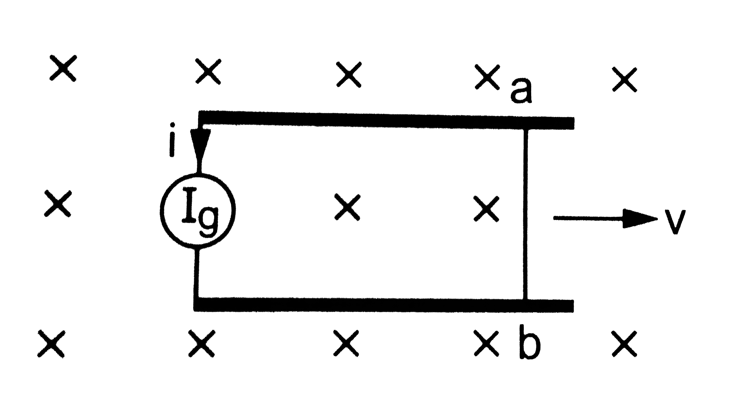
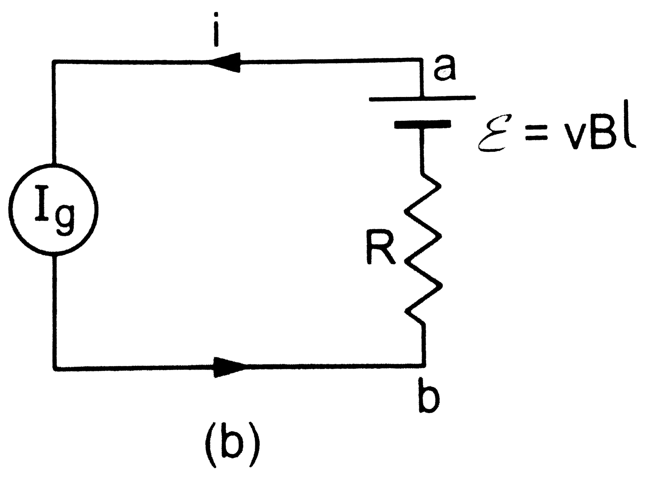
  6. Shows a wire ab of length l and resistance R which can slide on a smoo...

    Text Solution

    |

  7. A square loop of side 10 cm and resistance 1 Omega is moved towards ri...

    Text Solution

    |

  8. A metal rod length l rotates about on end with a uniform angular velo...

    Text Solution

    |

  9. Shows a conducting circular loop radius a placed in a uniform, perpend...

    Text Solution

    |

  10. shows a conducitng loop abcdefa made of six segment ab, bc cd, de, ef ...

    Text Solution

    |

  11. A wire of mass m and length I can freely slide on a pair of parallel, ...

    Text Solution

    |

  12. An inductor coil stores 32 J of magnetic field energy and dissiopates ...

    Text Solution

    |

  13. A 12 V battery connected ot a 6 Omega, 10 H coil through a switch driv...

    Text Solution

    |

  14. A solenoid of inductance 50 mH and resistance 10 Omega is connected ...

    Text Solution

    |

  15. An LR circuit having L = 4.0 H, R = 1.0 Omega and epsilon = 6.0 V is s...

    Text Solution

    |

  16. An LR combination is connected to an idal battery. If l = 10 mH, R = ...

    Text Solution

    |

  17. An inductor-resistance -battery circuit is switched on at t = 0. If th...

    Text Solution

    |

  18. A coil of inductance 1.0 H and resistance 100 Omega is connected to a...

    Text Solution

    |

  19. An inductance L and a resistance R are connected in series with a batt...

    Text Solution

    |

  20. Two conducting circular loops of radii R1 and R2 are placed in the sa...

    Text Solution

    |