Text Solution
Verified by Experts


Topper's Solved these Questions
Similar Questions
Explore conceptually related problems
HC VERMA-SEMICONDUCTOR AND SEMICONDUCTOR DEVICES-Exercises
- In a p-n junction, the depletion region is 400nm wide and and electric...
Text Solution
|
- The potential barrier exists across the junction is 0.2volt.What minim...
Text Solution
|
- In a p-n junction,a potential barrier of 250 mev exsists across the ju...
Text Solution
|
- When a p-n junction is reverse-biased,the current becomes almost const...
Text Solution
|
- The drift current in a p-n junction is 2.0(mu)A. Estimate the number o...
Text Solution
|
- The current-voltage characteristic of an ideal p-n junction diode is g...
Text Solution
|
- Consider a p-n junction diode having the characterstic i=i0(e^eV//kT-1...
Text Solution
|
- Calculate the current through the circuit and the petential difference...
Text Solution
|
- Each of the resistance shown in figure has a value of 20 Omega.Find th...
Text Solution
|
- Find the current through the resistance in the circuits shown in figur...
Text Solution
|
- What are the readings of the ammeterA1and A2shown in figure.Neglect th...
Text Solution
|
- Find the curent through the battery in each of the circuit shown in fi...
Text Solution
|
- Find the current through the resistance R in figure.If (a)R=12 Omega(b...
Text Solution
|
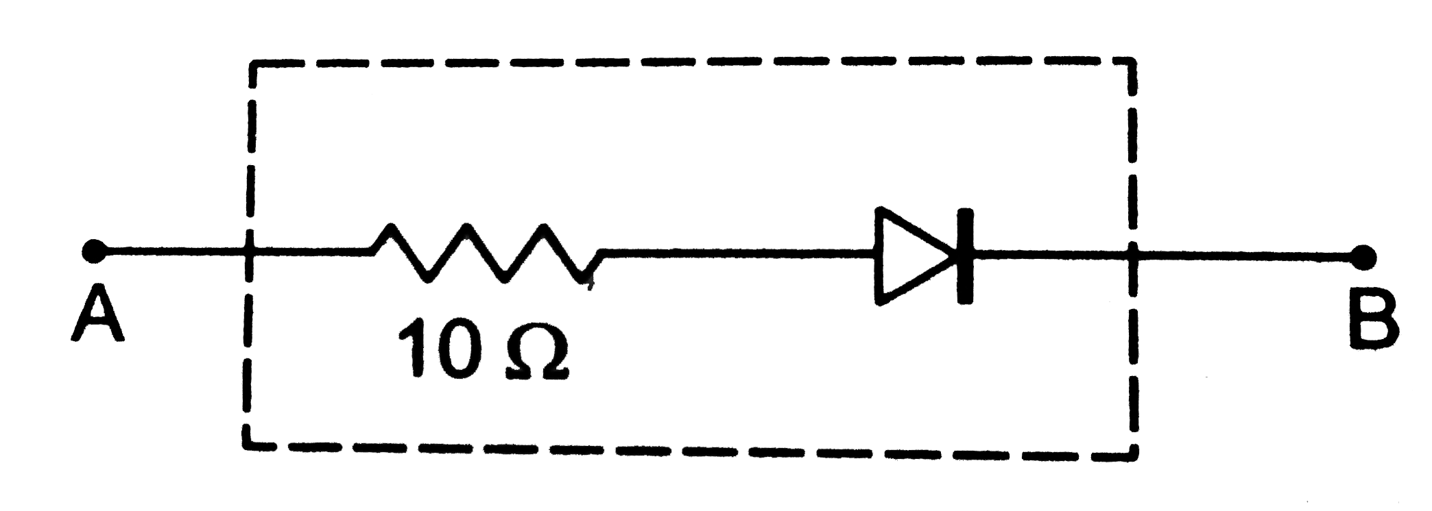
- Draw the current-voltage characteristics for the device shown in figur...
Text Solution
|
- Find the equivalent resistance of the network shown in figure
Text Solution
|
- When the base current in a transistor is changed from 30 mu Ato 80 mu ...
Text Solution
|
- A load resistor of 2 k Omega is connected in the collector branch of a...
Text Solution
|
- Let X=A bar(BC)+B bar(CA)+C bar(AB).Evalute X for (a)A=1,B=0,C=1 ...
Text Solution
|
- Design a logical circuit using AND, OR and NOT gates to evaluate A bar...
Text Solution
|
- Show that AB+bar(AB)is always 1.
Text Solution
|