A
B
C
D
Text Solution
Verified by Experts
The correct Answer is:


Topper's Solved these Questions
ELECTROSTATICS
ERRORLESS|Exercise PAST YEARS QUESTIONS|56 VideosELECTROSTATICS
ERRORLESS|Exercise ASSERTION & REASON|25 VideosELECTROSTATICS
ERRORLESS|Exercise NCERT BASED QUESTIONS (Capacitance)|59 VideosELECTRONICS
ERRORLESS|Exercise Assertion & Reason|26 VideosMAGNETIC EFFECTS OF CURRENT
ERRORLESS|Exercise ASSERTION & REASON |18 Videos
Similar Questions
Explore conceptually related problems
ERRORLESS-ELECTROSTATICS-NCERT BASED QUESTIONS (Grouping of Capacitors)
- Two condensers, one of capacity C and the other of capacity C/2 , are ...
Text Solution
|
- The equivalent capacitance of three capacitors of capacitance C(1):C(2...
Text Solution
|
- In the circuit shown in figure, each capacitor has a capacity of 3muF ...
Text Solution
|
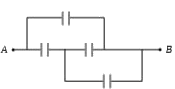
- The effective capacity between A and B in the figure given is
Text Solution
|
- Three capacitors each of capacity 4 muF are to be connected in such a ...
Text Solution
|
- Two identical parallel plate capacitors of capacitance C each are conn...
Text Solution
|
- A parallel plate capacitor with air as medium between the plates has a...
Text Solution
|
- An electric circuit requires a total capacitance of 2mF across a poten...
Text Solution
|
- All capacitors used in the diagram are identical and each is of capaci...
Text Solution
|
- Four identical capacitors are connected as shown in diagram. When a ba...
Text Solution
|
- A parallel plate capacitor with air as the dielectric has capacitance ...
Text Solution
|
- Consider a parallel plate capacitor of 10 muF (micro-farad) with air f...
Text Solution
|
- A gang capacitor is formed by interlocking a number of plates as shown...
Text Solution
|
- In the following diagram, the charge and potential difference across 8...
Text Solution
|
- The charge on any of the 2 muF capacitors and 1 muF capacitor will be ...
Text Solution
|
- Five capacitors of 10 muf capacity each are connected to a.d.c potenti...
Text Solution
|
- In the following figure, the charge on each condenser in the steady st...
Text Solution
|
- A parallel plate capacitor with air between the plates has capacitance...
Text Solution
|
- Two capcitors, 3 muF and 4 muF, are individually charged across a 6 V ...
Text Solution
|
- In the figure a capacitor is filled with dielectrics. The resultant ca...
Text Solution
|