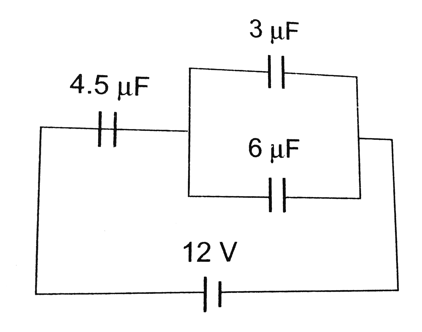
A
B
C
D
Text Solution
Verified by Experts
The correct Answer is:


Topper's Solved these Questions
Similar Questions
Explore conceptually related problems
ERRORLESS-ELECTROSTATICS-PAST YEARS QUESTIONS
- The electrostatic force between the metal plate of an isolated paralle...
Text Solution
|
- A parallel plate capacitor of capacitance 20 mu F is being charged by ...
Text Solution
|
- A parallel plate condenser is filled with two dielectrics as shown. Ar...
Text Solution
|
- Five capacitors, each of capacitance value C are connecteed as shown i...
Text Solution
|
- In the circuit shown in the figure, the potential difference across th...
Text Solution
|
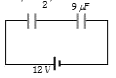
- Three capacitors of capacitance 3 muF, 10 muF and 15 muF are connected...
Text Solution
|
- A parallel plate capacitor is made by stacking n equally spaced plates...
Text Solution
|
- The electric potential of earth is taken to be zero because earth is a...
Text Solution
|
- A network of four capacitors of capacity equal to C(1) = C, C(2) = 2C,...
Text Solution
|
- A capacitor of 2 mu F is charged as shown in the diagram. When the swi...
Text Solution
|
- A spherical conductor of radius 10 cm has a charge of 3.2 x 10^-7 C di...
Text Solution
|
- In certain region of space with volume 0.2 m^3 the electric potential ...
Text Solution
|
- The capacitance of a parallel plate capacitor with air as Medium is 6 ...
Text Solution
|
- A short electric dipole has dipole moment of 16 x 10^-9 C m. The elect...
Text Solution
|
- Polar molecules are the molecules:
Text Solution
|
- Two charged spherical conductors of radius R1 and R2 are connected by ...
Text Solution
|
- The equivalent capacitance of the combination shown in the figure is
Text Solution
|
- A dipole is placed in an electric field as shown. In which direction w...
Text Solution
|
- A parallel plate capacitor has a uniform electric field vec(E) in the ...
Text Solution
|
- Twenty seven drops of same size are charged at 220V each. They combine...
Text Solution
|