A
B
C
D
Text Solution
Verified by Experts
The correct Answer is:


Topper's Solved these Questions
ELECTRONICS
ERRORLESS|Exercise Past years questions|73 VideosELECTRONICS
ERRORLESS|Exercise Assertion & Reason|26 VideosELECTRONICS
ERRORLESS|Exercise NCERT Based Questions (Junction Transistor)|29 VideosELECTRON, PHOTON, PHOTOELECTRIC EFFECT & X -RAY
ERRORLESS|Exercise ASSERTION & REASON|27 VideosELECTROSTATICS
ERRORLESS|Exercise ASSERTION & REASON|25 Videos
Similar Questions
Explore conceptually related problems
ERRORLESS-ELECTRONICS-NCERT Based Questions (Digital Electronics)
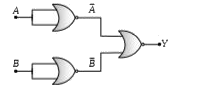
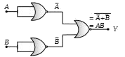
- Which logic gate is represented by following diagram
Text Solution
|
- The given figure shows the wave forms for two inputs A and B and that ...
Text Solution
|
- A researcher wants an alarm to sound when the temperature of air in hi...
Text Solution
|
- The figure shows a logic circuit with two inputs A and B and the outpu...
Text Solution
|
- The combination of gates shown below produces
Text Solution
|
- In the following circuit, the output Y for all possible inputs A and B...
Text Solution
|
- Digital circuit can be made by repetitive use of
Text Solution
|
- Identify the operation performed by the circuit given below
Text Solution
|
- For the given combination of gates, if the logic states of inputs A,B,...
Text Solution
|
- The circuit diagram (see fig.) shows a 'logic combination' with the st...
Text Solution
|
- Figure gives a system of logic gates. From the study of truth table it...
Text Solution
|
- The diagram of a logic circuit is given below. The output F of the cir...
Text Solution
|
- In circuit in following fig. the value of Y is
Text Solution
|
- Truth table for the given circuit is
Text Solution
|
- The given truth table is
Text Solution
|
- The truth table for the following logic circuit is
Text Solution
|
- The following configuration of gate is equivalent to
Text Solution
|
- Sum of the two binary numbers (100010)(2) and (11011)(2) is
Text Solution
|
- The decimal equivalent of the binary number (11010.101)(2) is
Text Solution
|
- v34
Text Solution
|