A
B
C
D
Text Solution
Verified by Experts
The correct Answer is:


Topper's Solved these Questions
Similar Questions
Explore conceptually related problems
ERRORLESS-ELECTRONICS-Past years questions
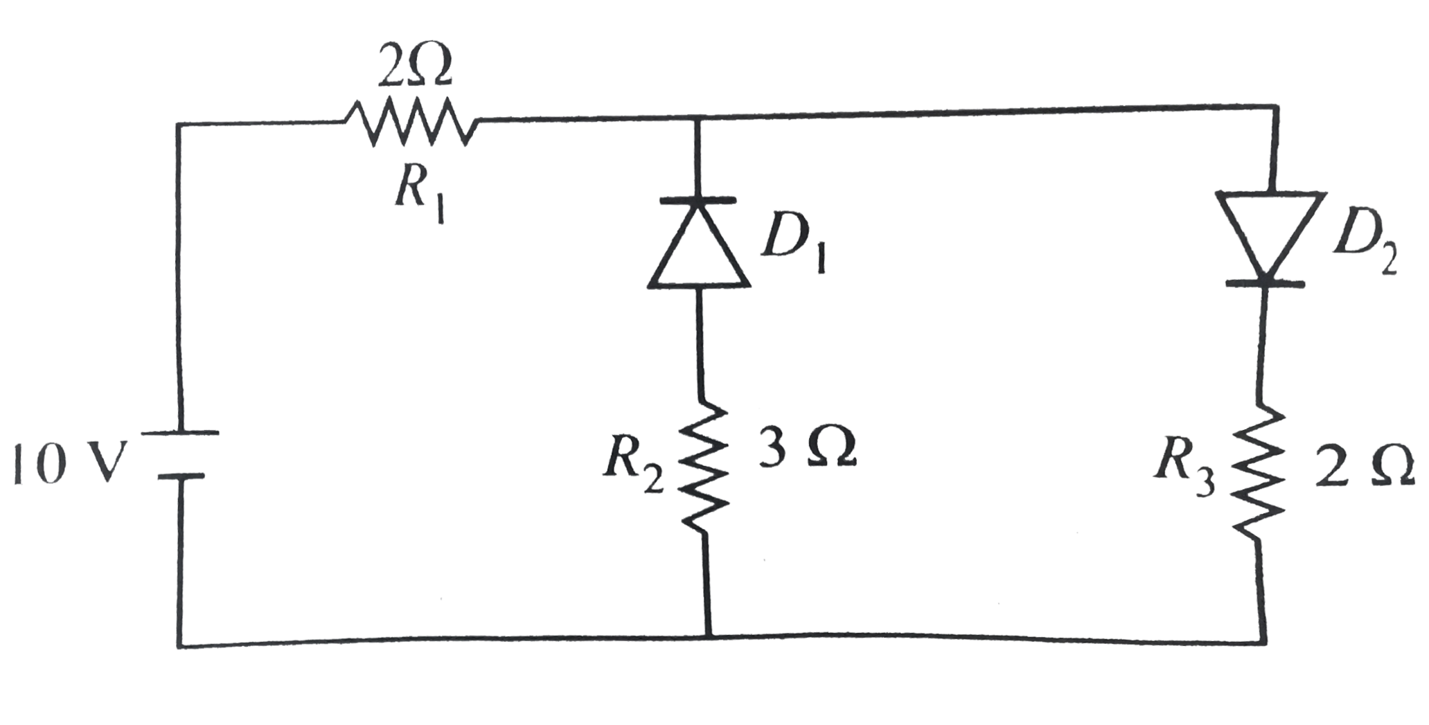
- Current in the circuit will be
Text Solution
|
- In the given figure, a diode D is connected to an external resistance ...
Text Solution
|
- The given circuit has two ideal diodes connected as show in the figure...
Text Solution
|
- Which one of the following represents forward bias diode?
Text Solution
|
- For transistor action which of the following statement are correct (...
Text Solution
|
- The minimum potential difference between the base and emitter required...
Text Solution
|
- One way in which the operation of an npn transistor differ from that o...
Text Solution
|
- In case of NPN-transistor the collector current is always less than th...
Text Solution
|
- A transistor is operated in common emitter configuration at V(c)=2 V s...
Text Solution
|
- In a common emitter transistor, the current gain is 80. What is the ch...
Text Solution
|
- Consider an n-p-n transistor amplifer in common-emitter configuration....
Text Solution
|
- An amplifier has a voltage gain A(V)=1000. The voltage gain in dB is
Text Solution
|
- A common emitter amplifier has a voltage gain of 50, an input impedanc...
Text Solution
|
- A common emitter amplifier gives an output of 3 V for an input of 0.01...
Text Solution
|
- The input resistance of a common emitter transistor amplifier, if the ...
Text Solution
|
- In a CE transistor amplifier, the audio signal voltage across the coll...
Text Solution
|
- In a common emitter (CE) amplifier having a voltage gain G, the transi...
Text Solution
|
- The input signal given to a CE amplifier having a voltage gain of 150 ...
Text Solution
|
- A n-p-n transisitor is connected in common emitter configuration in a ...
Text Solution
|
- In the following common emitter configuration an n-p-n transistor with...
Text Solution
|