A
B
C
D
Text Solution
Verified by Experts
The correct Answer is:


Topper's Solved these Questions
CURRENT ELECTRICITY
ERRORLESS|Exercise NCERT BASED QUESTIONS (KIRCHHOFF.S LAW, CELLS)|53 VideosCURRENT ELECTRICITY
ERRORLESS|Exercise NCERT BASED QUESTIONS (DIFFERENT MEASURING INSTRUMENTS) |74 VideosCURRENT ELECTRICITY
ERRORLESS|Exercise ASSERTION AND REASON|26 VideosATOMIC AND NUCLEAR PHYSICS
ERRORLESS|Exercise Assertion and Reason|23 VideosELECTROMAGNETIC INDUCTION
ERRORLESS|Exercise ASSERTION & REASON|20 Videos
Similar Questions
Explore conceptually related problems
ERRORLESS-CURRENT ELECTRICITY-NCERT BASED QUESTIONS (Grouping of Resistances)
- A parallel combination of two resistors, of 1 Omega each, is connected...
Text Solution
|
- In the circuit shown, the point B is earthed. The potential at the poi...
Text Solution
|
- The potential drop across the 3 Omega resistor is-
Text Solution
|
- A uniform wire of resistance 9 Omega is cut into 3 equal parts. They a...
Text Solution
|
- In the circuit shown below, the reading of the voltmeter V is-
Text Solution
|
- The current in a simple series circuit is 5.0 amp . When an additional...
Text Solution
|
- Figure showns a network of eight resistors numbered 1 to 8, each equal...
Text Solution
|
- In the circuit shown, the value of each resistance is r , then equival...
Text Solution
|
- A wire of resistance 10 Omega is bent to form a circle. P and Q are ...
Text Solution
|
- In the following circuit, bulb rated as 1.5 V, 0.45 W. If bulbs glows ...
Text Solution
|
- In the circuit shown, the current through 8 ohm is same before and aft...
Text Solution
|
- In circuit shown below, the resistance are given in ohms and the batte...
Text Solution
|
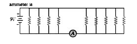
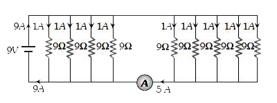
- If each resistance in the figure is of 9 Omega then reading of ammeter...
Text Solution
|
- Which arrangement of four identical resistances should be sued to draw...
Text Solution
|
- In the given circuit diagram, in the steady state the current through ...
Text Solution
|
- In the figure shown, the capacity of the condenser C is 2muC . The cur...
Text Solution
|
- The capacitor of capacitance C in the circuit shown in fully charged ...
Text Solution
|
- Consider the circuit shown in the figure below : All the resistor...
Text Solution
|
- The circuit shown has been connected for a long time. The voltage acro...
Text Solution
|
- What are the charges stored in the 1 muF and 2 muFcapacitors in the ci...
Text Solution
|