A
B
C
D
Text Solution
Verified by Experts
The correct Answer is:


Similar Questions
Explore conceptually related problems
Recommended Questions
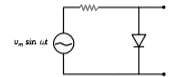
- The output of the given circuit in figure given below,
Text Solution
|
- The diagram of a logic circuit is given below. The output F of the cir...
Text Solution
|
- The output of the given circuit in figure given below,
Text Solution
|
- The output of the given circuit in figure:
Text Solution
|
- The output Y of the logic circuit given below is
Text Solution
|
- The output F of the logic circuit given below is
Text Solution
|
- Consider the circuit given below Chose the sketch depicting the output...
Text Solution
|
- The diagram of a logic circuit is given below. The output of the circu...
Text Solution
|
- The output Y of the logic circuit given below is
Text Solution
|