A
B
C
D
Text Solution
Verified by Experts
The correct Answer is:


Similar Questions
Explore conceptually related problems
Recommended Questions
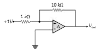
- In the circuit shown below, an input of 1V is fed into the inverting i...
Text Solution
|
- Input and output signal of an amplifier in CE configuration are always
Text Solution
|
- The real time variation of input signals A and B are as shown below. I...
Text Solution
|
- The logic circuit shown below has the input waveform 'A' and 'B' as sh...
Text Solution
|
- The real time variation of input signals A & B are as shown below. If ...
Text Solution
|
- ट्रान्जिस्टर के उभयनिष्ठ उत्सर्जक प्रवर्धक परिपथ के लिए निवेशी एवं निर...
Text Solution
|
- उभयनिष्ठ उत्सर्जक प्रवर्धक में निवेशी सिग्नल और निर्गत सिग्नल में .......
Text Solution
|
- The inputs to the digital circuit are shown below. The output Y is
Text Solution
|
- input are given as shown then output signal is-
Text Solution
|